Terminal and terminal-equipped electric wire

a technology of electric wire and terminal, which is applied in the direction of electrical equipment, connection contact material, and permanent deformation-induced connections, etc., can solve the problems of reducing damage and breakage of the insulating cover, and difficult to increase the crimping strength of the insulation barrel. achieve the effect of high retention strength

Active Publication Date: 2018-05-15
AUTONETWORKS TECH LTD +2
View PDF10 Cites 1 Cited by
  • Summary
  • Abstract
  • Description
  • Claims
  • Application Information

AI Technical Summary

Benefits of technology

[0015]When the crimping pieces are strongly crimped on the insulating cover, there may be cases where, during the crimping, the insulating cover is pushed and caught between the tip end portions of the pair of crimping pieces. But, providing such inclined portions makes it possible for the portion that would have come close to being caught to escape into a mountain-shaped region enclosed by the pair of inclined portions, and be prevented from being caught.
[0016]According to the technique disclosed in the present description, it is possible to achieve a terminal and a terminal-equipped electric wire in which crimping pieces have high retention strength.

Problems solved by technology

However, such a small-diameter aluminum electric wire has low impact resistance, and thus its portion crimped by the wire barrel is relatively easy to break if the wire connected to the terminal is subjected to a large impact.
However, if the insulation barrel undergoes high compression when being crimped on the insulating cover in order to increase its retention strength, the following problems will arise.
This may result in a disadvantage in that the insulating cover is damaged and broken if the wire is abruptly drawn to the rear.
Therefore, in the overlapping type, it is difficult to increase the crimping strength of the insulation barrel.
Furthermore, in another type in which a pair of insulation barrel pieces are arranged shifted with respect to each other in a direction in which the electric wire extends, and are pressed against each other at different positions located frontward and rearward, it is difficult to press the insulation barrel pieces against each other with a uniform force over the entire portion in the circumferential direction of the insulating cover, and thus there is the problem that no sufficient retention strength can be obtained.
As described above, it is difficult to increase the retention strength of the insulation barrels of both types.

Method used


Image

  • Terminal and terminal-equipped electric wire
  • Terminal and terminal-equipped electric wire
  • Terminal and terminal-equipped electric wire

Examples


Embodiment Construction

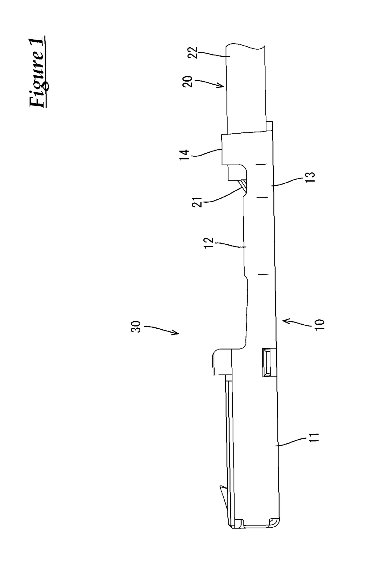
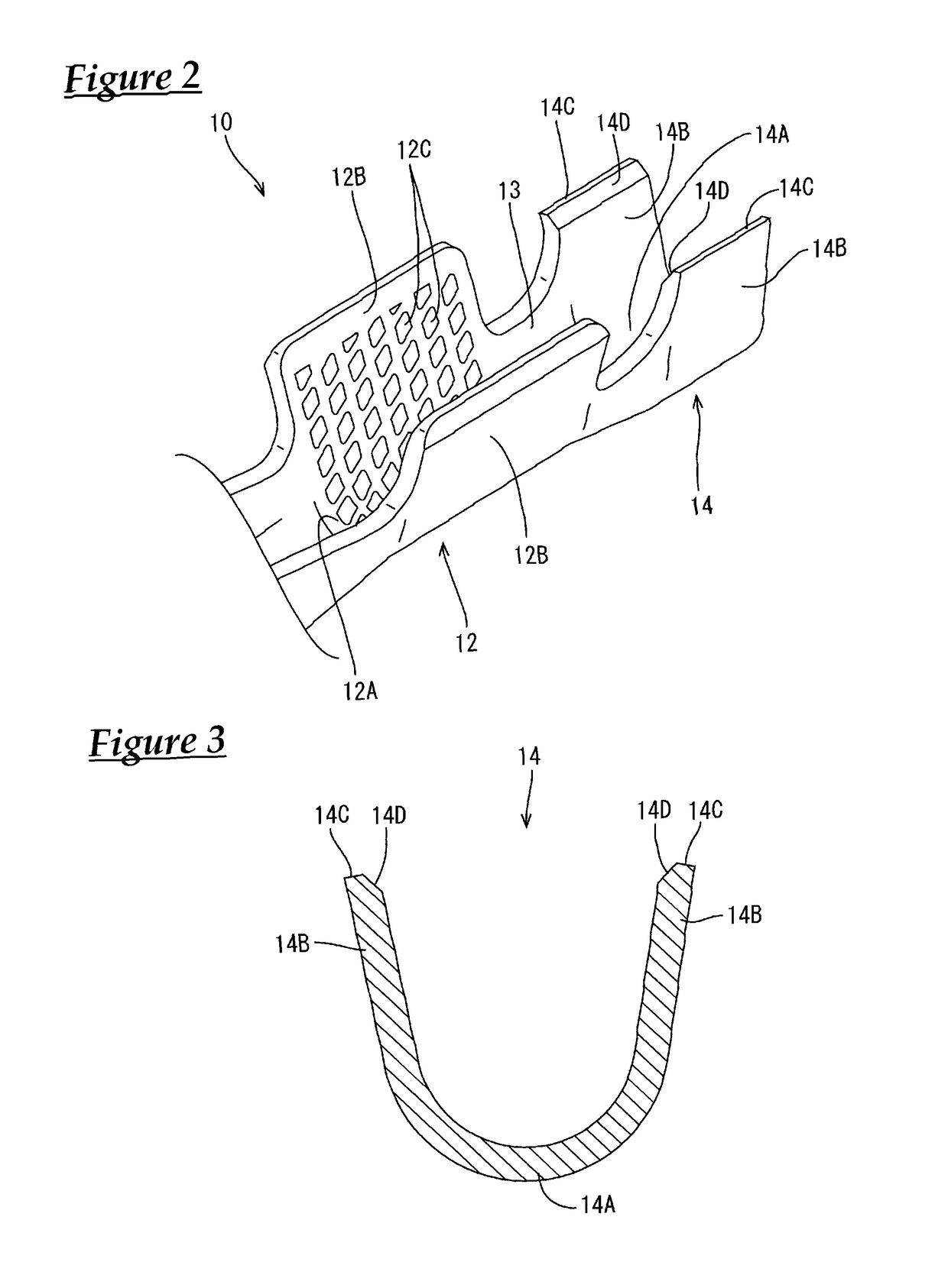
[0023]One embodiment will be described with reference to FIGS. 1 to 5.

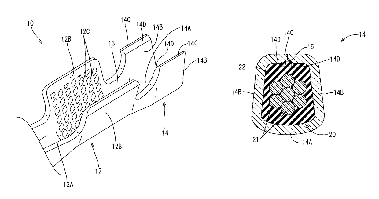
[0024]The present embodiment shows an example of a terminal-equipped electric wire 30 that is laid in a vehicle, for example. This terminal-equipped electric wire 30 is configured to include a female terminal 10, and an aluminum electric wire 20 that is connected to the female terminal 10, and is drawn rearward from the female terminal 10 (see FIG. 1). Note that in the following description, “front” refers to the left side of FIG. 1, “rear” refers to the right side, “upper” refers to the upper side, and “lower” refers to the lower side. Furthermore, “left” refers to the lower right of FIG. 2, and “right” refers to the upper left.

[0025]The aluminum electric wire 20 has a structure in which its core wires 21 are made of stranded wires obtained by twisting together a plurality of bar wires made of aluminum or an aluminum alloy, and are covered with an insulating cover 22 made of a synthetic resin. The insulating cove...


PUM


Abstract

A terminal that is connected to an end of an aluminum electric wire obtained by covering core wires with an insulating cover. The terminal is provided with a pair of insulation barrel pieces (crimping pieces) that extend in directions that intersect the longitudinal direction of the aluminum electric wire, and are crimped to the outer circumferential surface of the insulating cover. The pair of insulation barrel pieces have tip end portions that face and abut against each other in a state in which the pair of insulation barrel pieces are crimped to the insulating cover.

Description

CROSS REFERENCE TO RELATED APPLICATIONS[0001]This application claims the priority of Japanese patent application JP2015-084268 filed on Apr. 16, 2015, the entire contents of which are incorporated herein.TECHNICAL FIELD[0002]The technique disclosed in the present description relates to a terminal and a terminal-equipped electric wire.BACKGROUND ART[0003]In recent years, in the field of, for example, wire harnesses such as those for automobiles, aluminum electric wires have been used to save weight and the like. Aluminum electric wires have a structure in which their core wires are made of, for example, stranded wires obtained by twisting a plurality of aluminum bar wires together, and are covered with an insulating cover. If the aluminum electric wires are bundled into harnesses, terminals are typically connected to ends of the electric wires. Specifically, the insulating cover of an aluminum electric wire is stripped at an end so that ends of the core wires are exposed, and a wire ...

Claims


Application Information

Patent Timeline
Patent Type & Authority Patents(United States)
IPC IPC(8): H01R4/18
CPCH01R4/185H01R4/188H01R4/62
Inventor SHIMADA, TAKANOBUOOTSUKA, TAKUJIYOKOYAMA, YOSHIHISAHAMAGUCHI, TAKAHIKONAKATA, TAKEHIROMORIKAWA, SATOSHIHAMADA, HIROSHIHIRAI, HIROKIONO, JUNICHI
Owner AUTONETWORKS TECH LTD
Why Eureka
Try Eureka