
Air Conditioning Cushion for Wheelchair

a technology for wheelchairs and cushions, applied in wheelchairs/patient conveyances, applications, sofas, etc., to achieve the effects of reducing the risk of skin breakdown, ensuring comfort and support, and avoiding unsanitary and moist conditions on the skin of users

Inactive Publication Date: 2007-12-27
AIRERX HEALTHCARE
View PDF6 Cites 20 Cited by
  • Summary
  • Abstract
  • Description
  • Claims
  • Application Information

AI Technical Summary

Benefits of technology

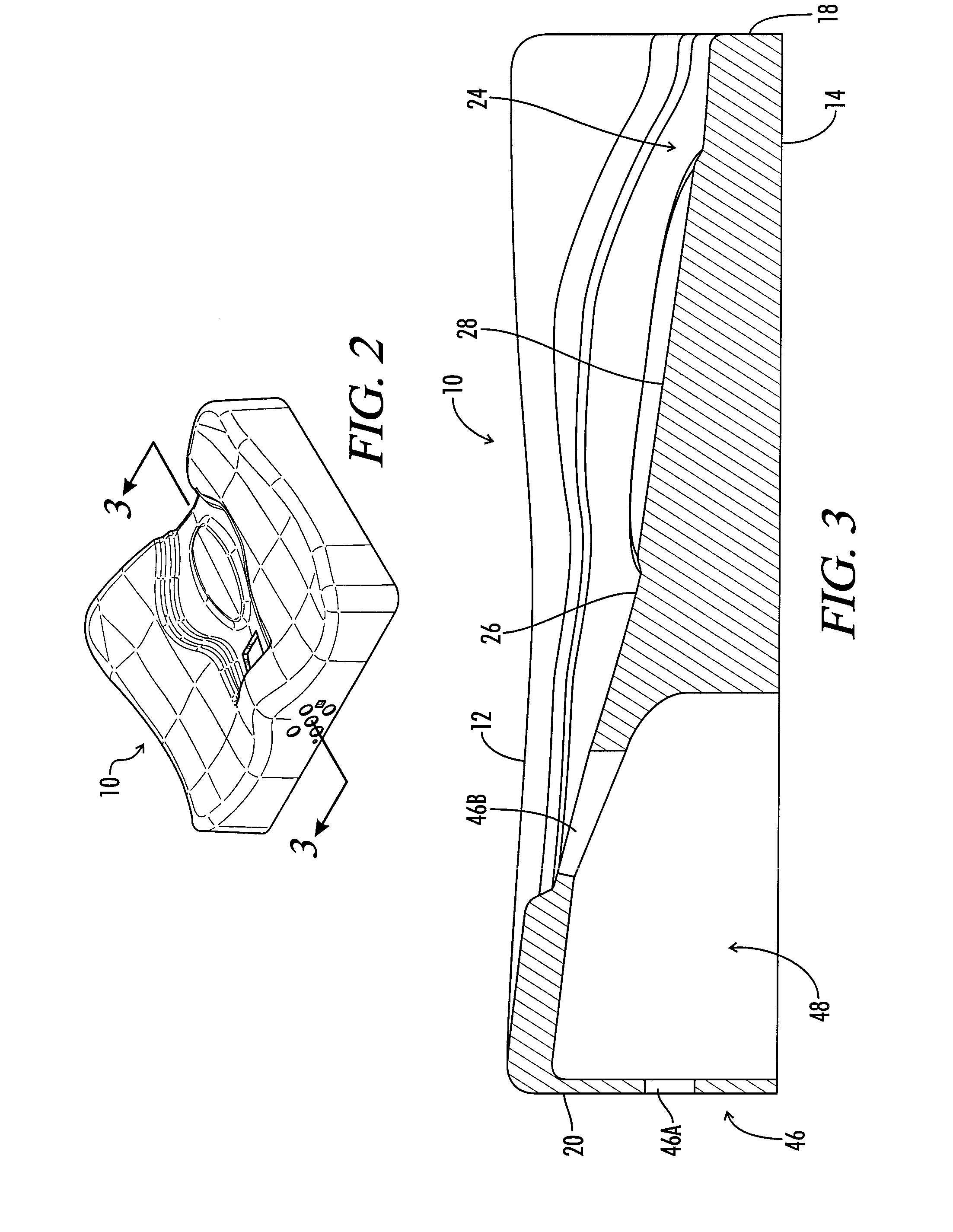
[0008]The present invention is directed to a seat cushion that delivers air to a user and removes moisture. In one embodiment of the invention, an indentation is formed into the center of the top of a foam pad and an air channel is formed through the foam pad, communicating between one of the sides of the foam pad and the indentation. In the air channel a cavity is formed and a chamber subassembly is inserted therein. This chamber subassembly has apertures on two of the sides and serves to maintain the viability of the channel after a user compresses the foam pad. Air naturally circulates through the air channel, through the chamber assembly, and into the indentation, which is filled with a permeable mesh. This permeable mesh insert allows the air to flow freely, while maintaining a comfortable level of support for the user, with the added benefit of allowing incontinence liquid to flow out through the insert drain through the indentation.
[0010]It is an object of this invention to augment the comfort and support of one sitting, especially one sitting for prolonged period in a wheelchair.
[0011]It is further an object of this invention to drain incontinence fluid released from a body of a user to avoid unsanitary and moist conditions on the skin of the user and to mitigate the risks of consequent skin breakdown.
[0012]It is another object of this invention to deliver conditioned air to the skin of the user to cool and dry the skin of the user to reduce the formation of skin ulcers and pressure sores.

Problems solved by technology

However, the above described systems suffer from the drawbacks of an inability to combine functions of cooling and handling incontinence material, and utilization of an insufficient and weak cooling system; thus there is a need for a seat cushion that can convectively cool the skin of a user, receive and remove the byproducts of incontinence, and provide additional, comfortable support.

Method used


Image

  • Air Conditioning Cushion for Wheelchair
  • Air Conditioning Cushion for Wheelchair
  • Air Conditioning Cushion for Wheelchair

Examples


Embodiment Construction

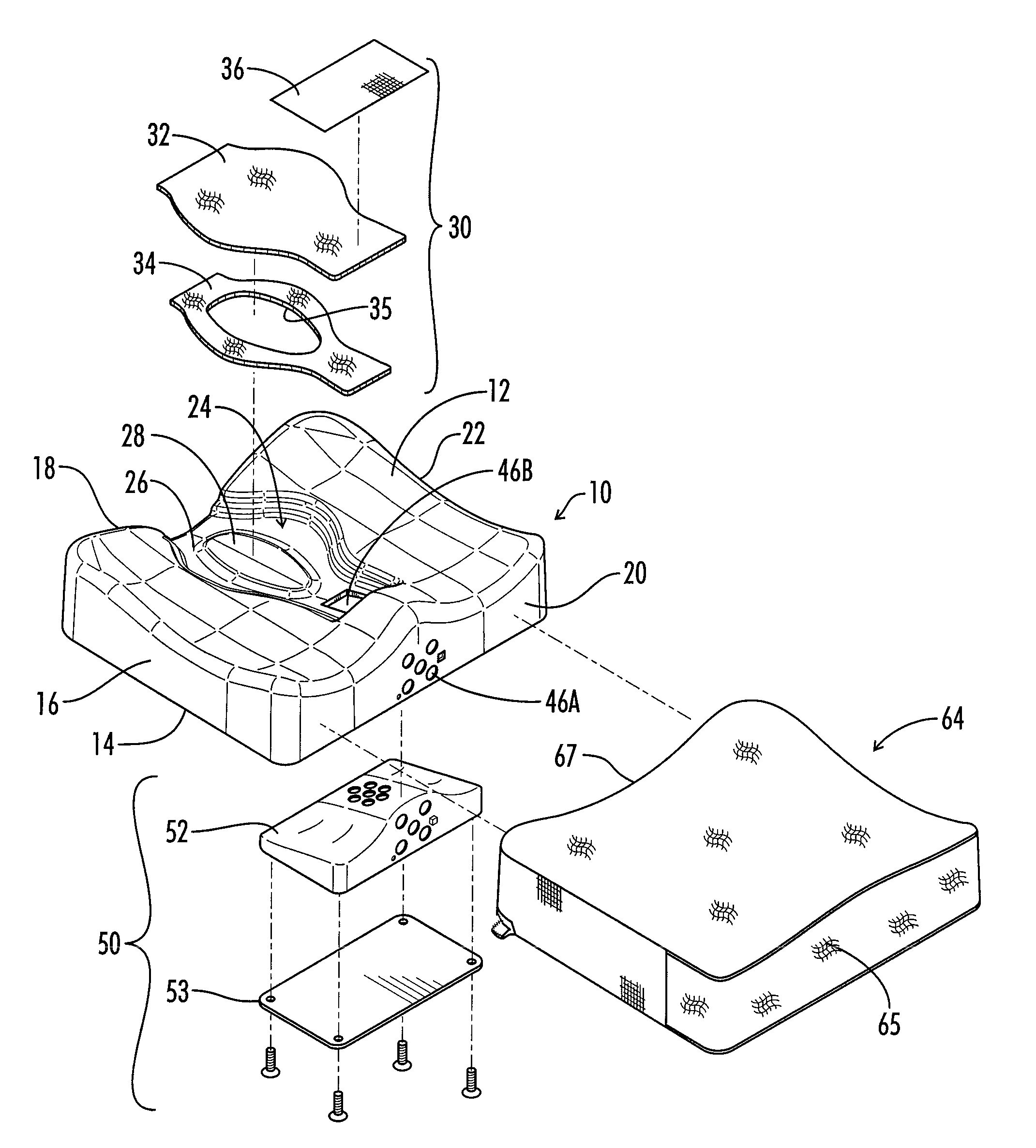
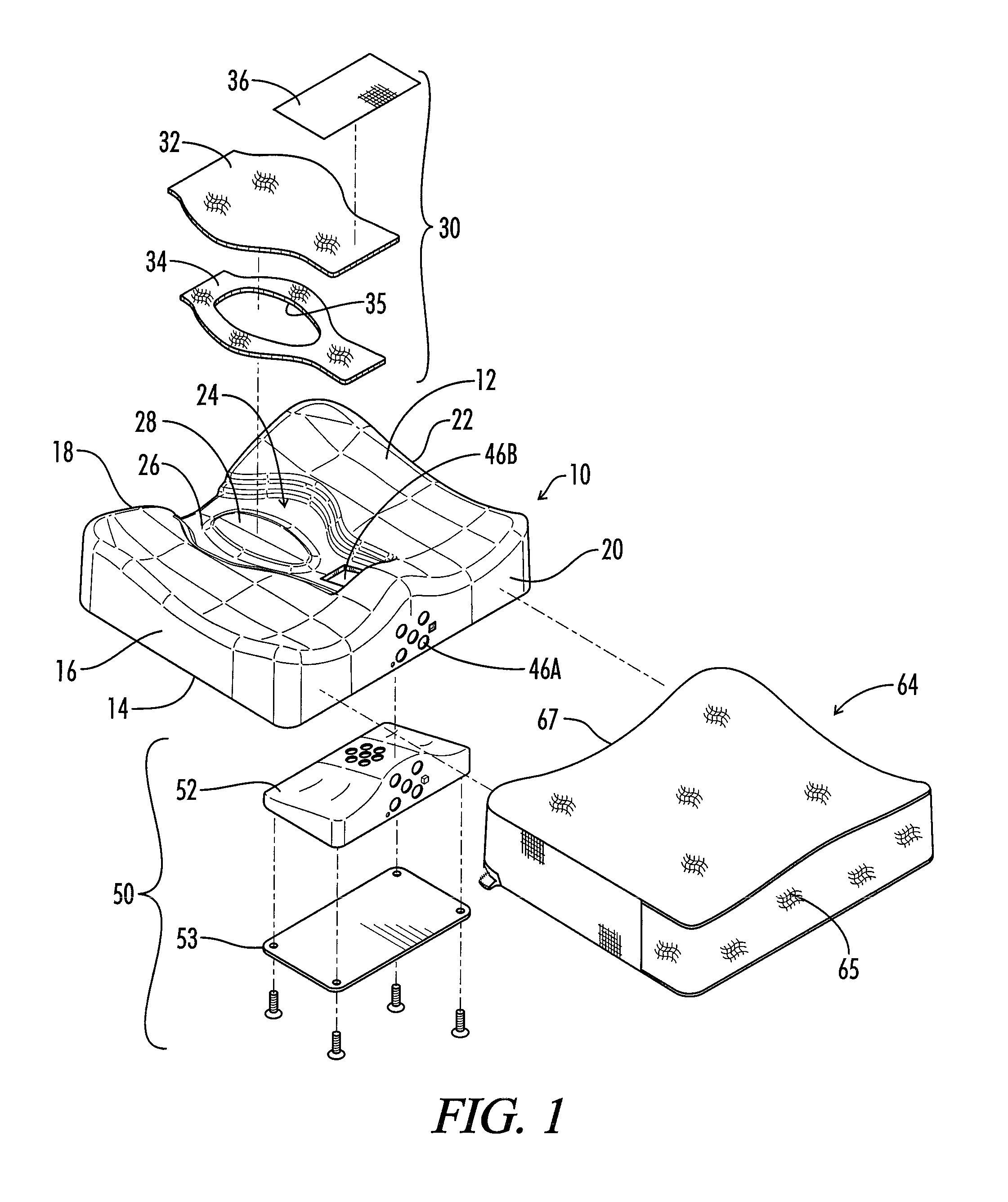
[0021]With reference to the drawings, FIG. 1 shows a seat cushion comprising a foam pad 10 formed with a metal mold; however, other molds or methods of construction could be used to achieve the shape and function of this foam pad 10. The foam pad 10 is constructed of foam that gently compresses to comfortably support the user and is coated with a material that is substantially impervious to liquid. The foam pad 10 further has a top 12, which is contoured to the anatomy of a user when the user is sitting on the seat cushion, a bottom 14, a side 16, a back side 18, a front side 20, and a side 22.

[0022]Formed into the top 12 of the foam pad 10 is an indentation 24, which, in the preferred embodiment, has a roughly concave surface 26. However, alternatively shaped surfaces that comfortably support the user, which receive and drain incontinence fluids, will suffice. The indentation 24 is sloped away from the front side 20 and towards the back side 18, such that fluids received into the i...


PUM


Abstract

A seat cushion for use in a wheel chair includes a foam pad contoured to the anatomy of a user positioned thereon and has an indentation in the middle thereof, which receives and drains incontinence fluid from the user. The foam pad encloses an air channel between the indentation and at least one side of the foam pad. A fan housed inside the pad pushes air through the air channel, into the indentation and onto the user. Alternatively, the seat cushion may house an air conditioner to circulate cooled air to the skin of the user.

Description

CROSS REFERENCE TO RELATED APPLICATION[0001]This application is based on U.S. Provisional Patent Application Ser. No. 60 / 816,834, filed Jun. 27, 2006, and claims priority based on the earlier filed provisional patent application, the entire disclosure of which is incorporated herein by reference.BACKGROUND[0002]1. Field of the Invention[0003]This invention relates to a seat cushion; more specifically, a seat cushion that may be used in a wheelchair to drain incontinence fluid and deliver conditioned air to the skin of the user.[0004]2. Description of the Prior Art[0005]U.S. Pat. No. 4,923,248 teaches a cooled seat cushion having a bottom and a back. Both the bottom and the back have a series of air passageways forming a plenum. This plenum is fed air from a Peltier unit which is attached to a DC power source, preferably a cigarette lighter in a car. The air passageways of the plenum are constructed of wound metallic coils; the passageways crisscross throughout the interior of both t...

Claims


Application Information

Patent Timeline
Patent Type & Authority Applications(United States)
IPC IPC(8): A47C27/00
CPCA61G2210/70A61G2007/05784A61G2005/1045A61G5/1043A61G5/1045A61G7/05784
Inventor SIEKMAN, ALLEN R.PRITCHETT, BALLARD HILLYERMCVICKER, DANFORD, RICHARD KEITH
Owner AIRERX HEALTHCARE
Learn More