Anti-backlash gear system

a gear system and anti-backlash technology, applied in the field of gear systems, can solve the problems of affecting the precise and repeatable indexing and/or positioning of devices, unable to completely eliminate backlash from any practical gear train, and unable to achieve the effect of load sharing

Inactive Publication Date: 2007-12-27
RGT UNIV OF CALIFORNIA
View PDF48 Cites 23 Cited by
  • Summary
  • Abstract
  • Description
  • Claims
  • Application Information

AI Technical Summary

Benefits of technology

[0012] Accordingly and advantageously the present invention includes an anti-backlash system comprising a single drive pinion and motor, wherein the drive pinion is movably mounted between two idler gears. Under low torque operation, the pinion is moved radially to remove backlash. During high torque operation, the pinion becomes centered substantially midway between the idler gears, advantageously centered as close as is feasible to the line joining the centers of the idler gears. Such a central position for the pinion gear facilitates load sharing among the pinion and idler gears.

Problems solved by technology

Backlash results in a certain “looseness” in the gear train that hinders precise and repeatable indexing and / or positioning of the device or devices being driven by the gear train.
However, when gear trains are loaded in more than one direction of motion, for example when precise positioning and / or tracking is required as is typically the case for movable radio telescope or other receiving and / or transmitting antennas, then backlash becomes a concern.
While backlash can be reduced by using gear structures having very precise dimensional tolerances, backlash cannot be completely eliminated from any practical gear train and, indeed, it is typically not advisable to attempt to do so.
Severe wear or even binding of the gear train can result when very tightly meshed gears are employed in a gear train.
Thus, using precise dimensional tolerances as a means to eliminate backlash is not often a practical solution.
Backlash can be a particularly challenging problem when the positioning system experiences reversing and variable loads such as positioning a radio telescope, dish antenna and the like that may be subject to variable and shifting wind loading.
However, only one set of gears is available to carry the load while the second set of gears only provides anti-backlash.
Therefore, when the direction of an extreme load is unpredictable, such as wind loading of a radio telescope, both sets of gears must be designed with maximal loading in view.
However, this system has the disadvantage of requiring two motor and drive systems.

Method used


Image

  • Anti-backlash gear system
  • Anti-backlash gear system
  • Anti-backlash gear system

Examples


Embodiment Construction

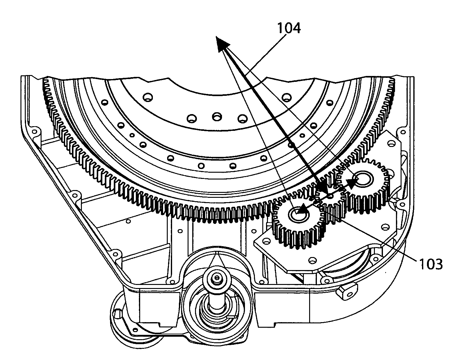
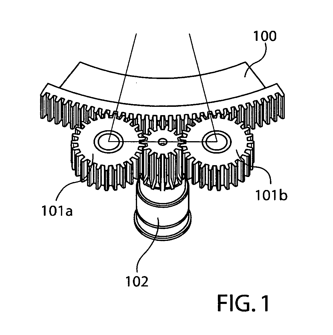
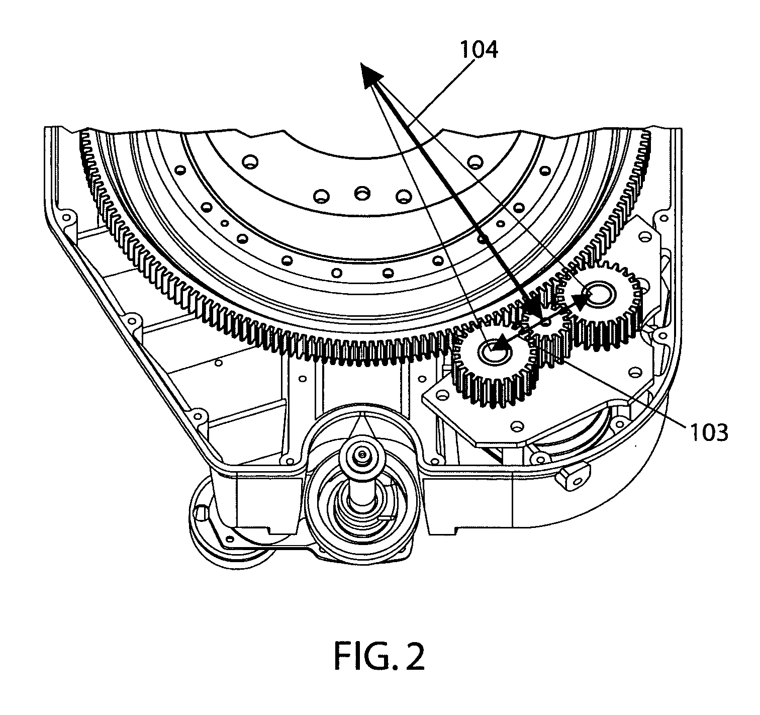
[0024] After considering the following description, those skilled in the art will clearly realize that the teachings of the invention can be readily utilized as an anti-backlash system in mechanical positioning systems such as radio telescopes among others.

[0025] In typical gear drive systems, it is advantageous in most applications for a small gap to be present between the teeth of any two meshing gears. Such a gap allows for manufacturing and installation tolerances as well as to facilitate lubrication. This gap can be reduced for very high precision parts, but severe wear can result if the gap is completely eliminated as the gear teeth are wedged into each other. This gap is called “backlash” and results in a certain “looseness” in the gear drive system that is particularly apparent when reversing direction of motion.

[0026] In power transmission systems, the gear teeth typically apply a force in only one circumferential direction so backlash is generally not a serious concern. ...


PUM


Abstract

An anti-backlash system comprising a single drive pinion and motor is disclosed. In an exemplary embodiment, the single drive pinion is situated between two idler gears and is allowed to move in the radial direction relative to the bull gear. A preload force provides for the substantial absence of backlash at low torque loads. The pinion moves to the center point between the two idler gears and balances the torque during high torque loads. The present anti-backlash system is well suited for use in drive and positioning systems that are subject to variable and reversing loads, such as those experienced by radio telescopes in variable wind conditions.

Description

BACKGROUND OF THE INVENTION [0001] 1. Field of Invention [0002] This invention relates generally to the field of gear systems and, more particularly, to a system for the reduction of backlash. [0003] Financial support from the SETI Institute, made possible by the Paul G. Allen Foundation, is gratefully acknowledged. [0004] 2. Description of the Prior Art [0005] Backlash in a gear system is the clearance between a gear tooth and its mating gap, or, in other words, the amount by which a gear tooth space exceeds the thickness of the engaging tooth, as measured along the pitch circle. Backlash results in a certain “looseness” in the gear train that hinders precise and repeatable indexing and / or positioning of the device or devices being driven by the gear train. When gear trains are loaded in only a single direction, backlash is typically not a concern. However, when gear trains are loaded in more than one direction of motion, for example when precise positioning and / or tracking is requ...

Claims


Application Information

Patent Timeline
Patent Type & Authority Applications(United States)
IPC IPC(8): F16H55/18
CPCF16H1/22F16H57/12Y10T74/19898F16H2057/121F16H2057/126
Inventor FLEMING, MATTHEW C.
Owner RGT UNIV OF CALIFORNIA
Why Eureka
Try Eureka