Light emitting diode with direct view optic

Inactive Publication Date: 2007-12-27
OSRAM SYLVANIA INC
View PDF30 Cites 87 Cited by
  • Summary
  • Abstract
  • Description
  • Claims
  • Application Information

AI Technical Summary

Benefits of technology

[0006]This construction couples the light guide to the output surface of the LED in a zero-gap relationship insuring that substantially all of the light emitted by the LED enters the input window of the lig

Problems solved by technology

The major problem that occurs in such constructions is the loss of light that is occasioned between the output surface of the LED and the inp

Method used


Image

  • Light emitting diode with direct view optic
  • Light emitting diode with direct view optic
  • Light emitting diode with direct view optic

Examples


Example

[0012]For a better understanding of the present invention, together with other and further objects, advantages and capabilities thereof, reference is made to the following disclosure and appended claims taken in conjunction with the above-described drawings.

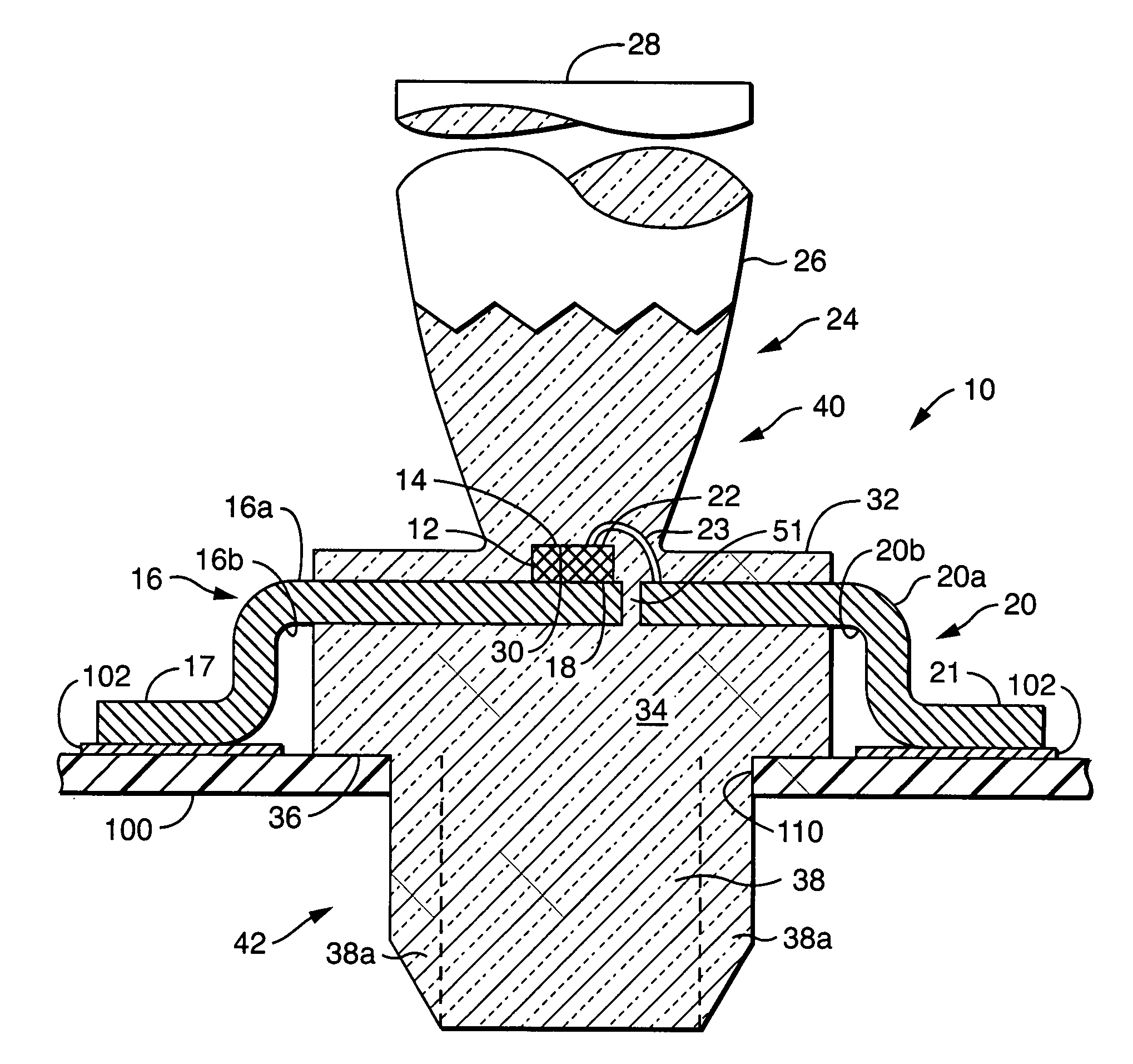
[0013]Referring now to the drawings with greater particularity, there is shown in FIG. 1 an LED and light guide assembly 10, comprising: an LED 12 with an output surface 14. A first power input lead 16 is electrically coupled to a first pole 18 of the LED 12. The first power input lead 16 has a first surface 16a and a second surface 16b. A second power input lead 20 is electrically coupled to a second pole 22 of the LED 12, for example, by a wire 23, and has a first surface 20a and a second surface 20b. The power input leads 16 and 20 are preferably formed from a material having a high thermal conductivity since they can function also as a heat sink. While many materials can thus qualify, fabrication of the power input leads from...


PUM


Abstract

An LED and light guide assembly has an LED with an output surface; a first power input lead electrically coupled to a first pole and having a first surface and a second surface; and a second power input lead electrically coupled to a second pole and having a first surface and a second surface. A unitary, molded light guide has an axially extending, light transmissive body with a light output window. An input window is formed with the unitary, molded light guide being aligned in a zero-gap relationship to capture substantially all the light emitted by the LED. A support is formed integral with the light guide and envelopes a portion of the first surface and the second surface of the first power input lead and the first surface and the second surface of the second power input lead to anchor the guide with respect to the power inputs.

Description

TECHNICAL FIELD[0001]This invention relates generally to light sources and more particularly to light emitting diode (LED) light sources. Still more particularly, it relates to LED light sources integrally combined with light guides.BACKGROUND ART[0002]LEDs have frequently been employed with various light modifying media such as optic fibers and light guides to direct, amplify or otherwise position the light output from the LED. The major problem that occurs in such constructions is the loss of light that is occasioned between the output surface of the LED and the input surface of the light modifying media. Even employing the best available optical binding agents and gels does not eliminate this loss effect. Therefore, it would be an advance in the art if this light loss could be eliminated or substantially reduced.DISCLOSURE OF THE INVENTION[0003]It is, therefore, an object of this invention to obviate the disadvantages of the prior art.[0004]It is another object of the invention t...

Claims


Application Information

Patent Timeline
IPC IPC(8): H01L33/00H01L21/00H01L33/54
CPCG02B6/4204H01L33/54H01L2224/48091H01L2224/48247H01L2224/45144H01L2924/00014H01L2924/00H01L2924/1815
Inventor COUSHAINE, CHARLES M.JOHNSON, RALPHTESSNOW, THOMAS
Owner OSRAM SYLVANIA INC
Why Eureka
Try Eureka