Resonant circuit tuning system using magnetic field coupled reactive elements

a reactive element and resonance circuit technology, applied in the field of electromechanical tuning circuits, can solve the problems of affecting tuning and performance, material change, and practicable limitations of high q lcr circuits

Inactive Publication Date: 2007-12-27
TYCO FIRE & SECURITY GMBH
View PDF14 Cites 44 Cited by
  • Summary
  • Abstract
  • Description
  • Claims
  • Application Information

AI Technical Summary

Problems solved by technology

There are practical limitations to the use of high Q LCR circuits.
For example, design tolerance variations in tuning may be caused by variations in the construction of the resonant capacitor(s) and variations in the construction of the antenna coil, which affect the inductance and resistance of the LCR circuit, thereby affecting tuning and performance.
Some materials may also change over time during the life of the system.
All these changes in material characteristics affect the inductance and the losses of the LCR circuit and affect tuning and performance.
The altering of the magnetic field can change both the inductance of the coil and the effective resistance of the LCR circuit, thereby affecting the tuning and performance of the LCR circuit.
As a result, this may cause the inductance or effective resistance of the antenna to dynamically change, thereby affecting the tuning and performance of the LCR circuit.
However, hi

Method used


Image

  • Resonant circuit tuning system using magnetic field coupled reactive elements
  • Resonant circuit tuning system using magnetic field coupled reactive elements
  • Resonant circuit tuning system using magnetic field coupled reactive elements

Examples


Embodiment Construction

[0028]For simplicity and ease of explanation, the invention will be described herein in connection with various embodiments thereof. Those skilled in the art will recognize, however, that the features and advantages of the various embodiment of the invention may be implemented in a variety of configurations. It is to be understood, therefore, that the embodiments described herein are presented by way of illustration, not of limitation.

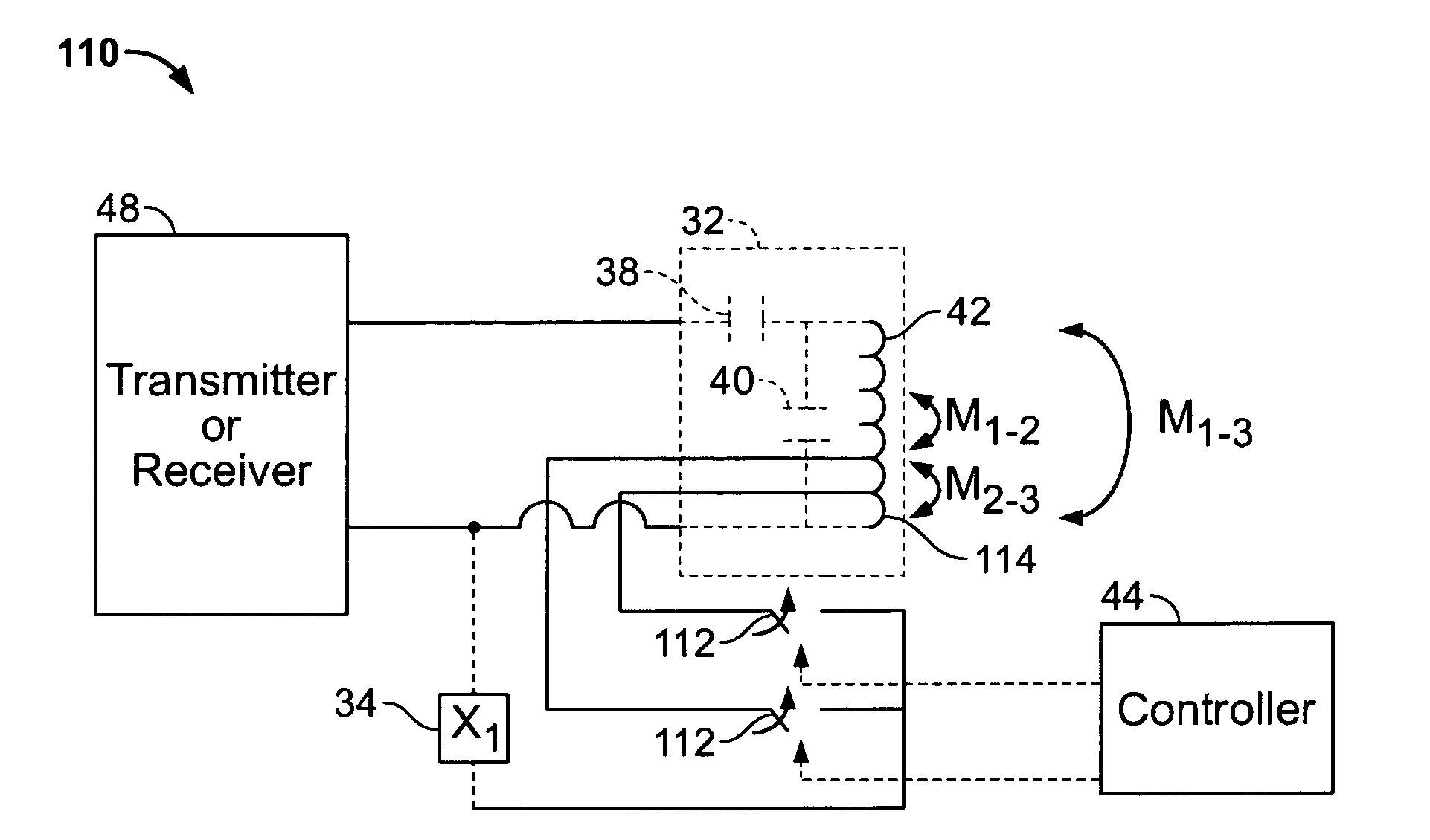
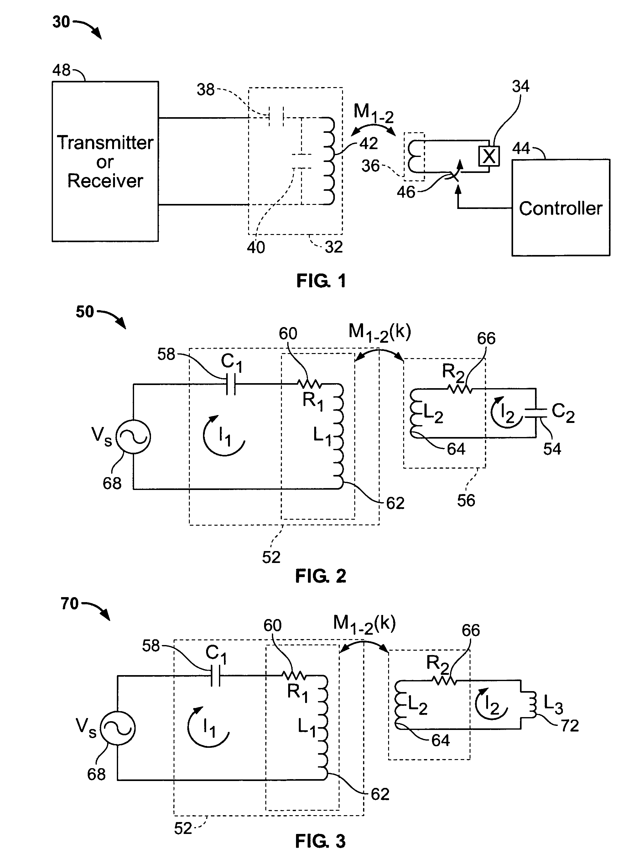
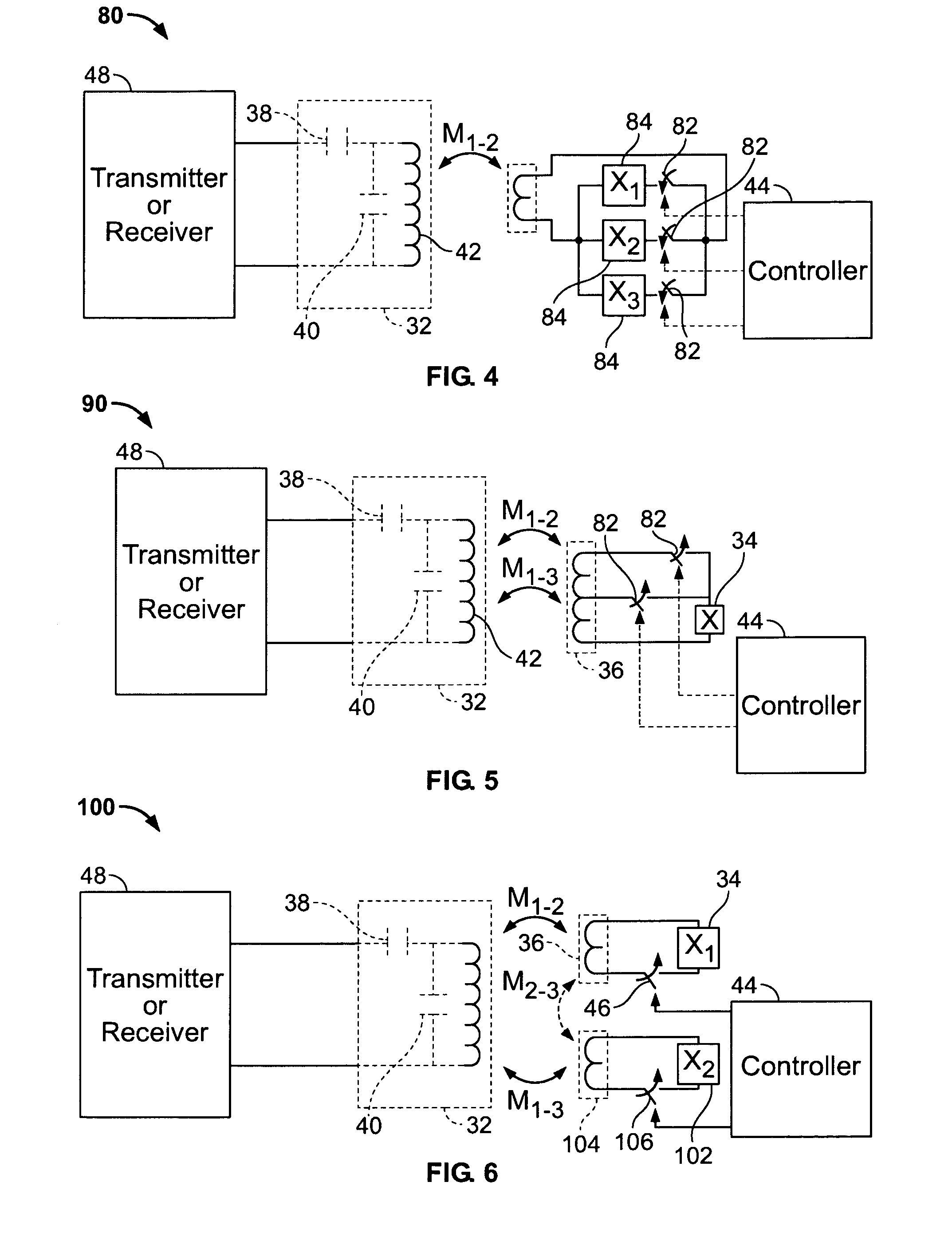
[0029]Various embodiments of the invention provide a system and method for tuning an LCR circuit using one or more magnetically coupled reactive elements and / or resistive elements. It should be noted that the tuning system and method may be used in connection with any type of electronic system, for example, in electronic systems wherein a coil is used as either a transmitter or receiver. The tuning system and method also may be used in different types of applications, for example, Electronic Article Surveillance (EAS), Radio Frequency Identification (R...


PUM


Abstract

A resonant circuit tuning system and a method for tuning are provided. The resonant circuit tuning system may include an LCR circuit and a reactive element magnetically coupled to the LCR circuit.

Description

BACKGROUND OF THE INVENTION[0001]1. Field of the Invention[0002]This invention relates generally to electronic tuning circuits, and more particularly to a tuning system using magnetic field coupled reactive elements.[0003]2. Description of the Related Art[0004]Magnetic fields are used in many electronic systems for a variety of purposes such as Electronic Article Surveillance (EAS), Radio Frequency Identification (RFID), metal detectors, magnetic imaging systems, remote sensing, communications, etc. In these various electronic systems, a magnetic coil may be used as either a transmitter or as a receiver. As a transmitter, the coil is usually employed to project a magnetic field into a desired sensing region. As a receiver, the coil may be placed in a region to receive a signal or to detect the presence of a tag, metal object, etc.[0005]More particularly, for transmitters, a highly efficient method for generating magnetic fields involves the use of a series resonant LCR circuit that ...

Claims


Application Information

Patent Timeline
IPC IPC(8): H04Q5/22
CPCH03J1/0008
Inventor HALL, STEWART E.HERRING, RICHARDPATTERSON, HAP
Owner TYCO FIRE & SECURITY GMBH
Why Eureka
Try Eureka