Little pole difference magnetic field coupling type magnetism transmission eccentricity gear pair of novel radial direction magnetic field

A technology of radial magnetic field and magnetic transmission, applied in electromechanical transmission devices, electric vehicles, electric components, etc., can solve the problems of reduced magnetic flux of permanent magnets, large amount of expensive rare earth materials, and consumption of rare earth permanent magnets, etc., to improve the unit torque density and power density, no mechanical wear, no lubrication effect

Inactive Publication Date: 2013-05-15
余虹锦
View PDF10 Cites 21 Cited by
  • Summary
  • Abstract
  • Description
  • Claims
  • Application Information

AI Technical Summary

Problems solved by technology

However, there are two fatal deficiencies in this magnetic gear designed based on the magnetic field modulation technology from the theoretical principle to the structural scheme: first, from a theoretical point of view, the number of poles (teeth) of the magnetic permeable grid core that plays the role of magnetic field modulation must be Satisfy the constraints, resulting in less than half of the permanent magnets of the magnetic gear being in the working state of mutual magnetic field coupling at any time during the transmission of the magnetic gear, and more than half of the permanent magnet poles are in the idle non-coupling state, that is, the utilization of rare earth permanent magnets The ratio is theore

Method used


Image

  • Little pole difference magnetic field coupling type magnetism transmission eccentricity gear pair of novel radial direction magnetic field
  • Little pole difference magnetic field coupling type magnetism transmission eccentricity gear pair of novel radial direction magnetic field

Examples


Embodiment Construction

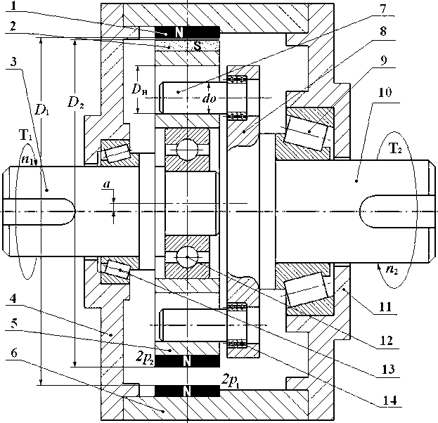
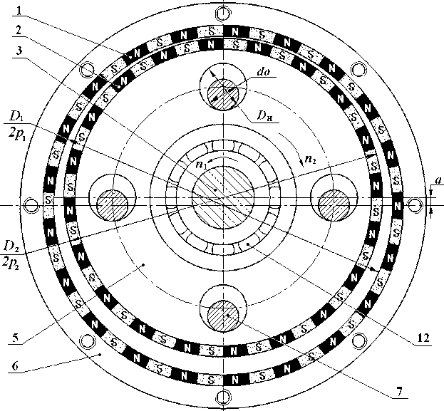
[0032] Below in conjunction with accompanying drawing and specific embodiment, the present invention will be further described: figure 1 It is a full cross-sectional view of the axial structure of the eccentric gear pair of the magnetic transmission eccentric gear pair with a new type of radial magnetic field with few pole difference magnetic field coupling, figure 2 It is a full section view of the radial structure of the eccentric gear pair of the magnetic transmission eccentric gear pair of a new type of radial magnetic field with few pole difference magnetic field coupling.

[0033] One, from figure 2 It can be seen that the working principle of the new radial magnetic field magnetic transmission eccentric gear pair with few polar differences is: the eccentric input shaft 3 drives the planetary rotor core 5 to revolve around the rotation axis, and the planetary rotor on the eccentrically revolving planetary rotor core 5 is permanently The magnet 2 and the stator permane...


PUM


Abstract

Disclosed is a little pole difference magnetic field coupling type magnetism transmission eccentricity gear pair of a novel radial direction magnetic field. The little pole difference magnetic field coupling type magnetism transmission eccentricity gear pair of the novel radial direction magnetic field can be applied widely in the field of industry transmissions of wind power generation, electric automobile, vessel driving and the like. The little pole difference magnetic field coupling type magnetism transmission eccentricity gear pair of the novel radial direction magnetic field is characterized in that a stator with a 2p1 stator permanent magnet 1 are distributed in the inner hole of a machine shell 6. A magnetism transmission gear pairs are formed by planet rotors of 2p2 planet rotor permanent magnet 2 are distributed on the excircle of a planet rotor iron core5. A number difference between the pole number 2p1 and 1p2 is small. The permanent magnets on the two magnetic gear pairs penetrate through an air gap magnetic field coupling of the radial direction eccentricity, and are connected to an eccentricity structure by the little pole difference two magnetic gear pairs. A second bearing 12 and a third bearing 13 are installed on an eccentricity input shaft 3. The planet rotor iron core 5 is driven by the eccentricity input shaft 3 to revolve in autogiration around the axis. A low speed autogiration of the planet rotor is output through a pin hole type output structure.

Description

technical field [0001] The present invention is a novel magnetic transmission eccentric gear pair with less pole difference magnetic field coupling type of radial magnetic field. It can directly replace the conventional mechanical gear transmission transmission system, and is widely used in wind power generation, hydropower generation, electric vehicles, ship drive and other industrial transmission fields that require direct drive. Background technique [0002] In many transmission fields of industrial applications, it is often necessary to realize the mutual conversion of low-speed, high-torque mechanical energy and high-speed, low-torque mechanical energy. High-speed mechanical kinetic energy for power generation, electric vehicles and submarine drives need to convert the high-speed mechanical power of the drive motor into mechanical power with very low speed and high torque. According to the existing conventional design technology, the extremely low speed and high torque...

Claims


Application Information

Patent Timeline
IPC IPC(8): H02K51/00
CPCY02T10/641H02K49/102Y02T10/64
Inventor 余虹锦
Owner 余虹锦
Why Eureka
Try Eureka