Wireless power transmission system

a power transmission system and wireless technology, applied in electromagnetic wave systems, transformers, inductances, etc., can solve the problems of reducing the efficiency of transmission from the power transmitting device to the power receiving device, unnecessary magnetic field coupling between the two power transmitting coils, etc., to inhibit magnetic flux, and suppress magnetic field coupling

Inactive Publication Date: 2015-08-06
ALPS ALPINE CO LTD
View PDF9 Cites 21 Cited by
  • Summary
  • Abstract
  • Description
  • Claims
  • Application Information

AI Technical Summary

Benefits of technology

[0036]Furthermore, the power receiving device includes the third magnetic substance placed on the first power receiving coil, and the fourth magnetic substance placed on the second power receiving coil. Therefore, by concentrating a magnetic flux generated by the first power receiving coil into the inside of the third magnetic substance, it is possible to suppress magnetic field coupling between the first power receiving coil and the second power receiving coil. In addition, by concentrating a magnetic flux generated by the second power receiving coil into the inside of the fourth magnetic substance, it is possible to suppress magnetic field coupling between the first power receiving coil and the second power receiving coil.
[0037]Furthermore, the third attachment surface and the fourth attachment surface are located on the upper side of the power receiving surface and are arranged on the same plane surface parallel to the power receiving surface. Therefore, it is possible to inhibit a magnetic flux radiated from the power transmitting coil toward the first power receiving coil from being blocked by the fourth magnetic substance. In addition, it is possible to effectively magnetic-field-couple the power transmitting coil and the first power receiving coil to each other. In addition, it is possible to inhibit a magnetic flux radiated from the power transmitting coil toward the second power receiving coil from being blocked by the third magnetic substance. In addition, it is possible to effectively magnetic-field-couple the power transmitting coil and the second power receiving coil to each other. As a result, it is possible to suppress a reduction of the efficiency of the transmission from the power transmitting device to the power receiving device.

Problems solved by technology

However, in such a method, if the two power transmitting coils are arranged so as to be situated close to each other, unnecessary magnetic field coupling is produced between the two power transmitting coils.
However, in such a method, if the two power receiving coils are arranged so as to be situated close to each other, unnecessary magnetic field coupling is produced between the two power receiving coils.
In addition, there is a possibility that a portion of an electric signal received by one power receiving coil of the two power receiving coils is transmitted to the other power receiving coil by the magnetic field coupling between the two power receiving coils and in association therewith, the efficiency of the transmission from the power transmitting device to the power receiving device is reduced.

Method used


Image

  • Wireless power transmission system
  • Wireless power transmission system
  • Wireless power transmission system

Examples


Embodiment Construction

[0048]The following description is intended to convey a thorough understanding of the embodiments described by providing a number of specific embodiments and details involving an antenna checking circuit. It should be appreciated, however, that the present invention is not limited to these specific embodiments and details, which are exemplary only. It is further understood that one possessing ordinary skill in the art, in light of known systems and methods, would appreciate the use of the invention for its intended purposes and benefits in any number of alternative embodiments, depending on specific design and other needs.

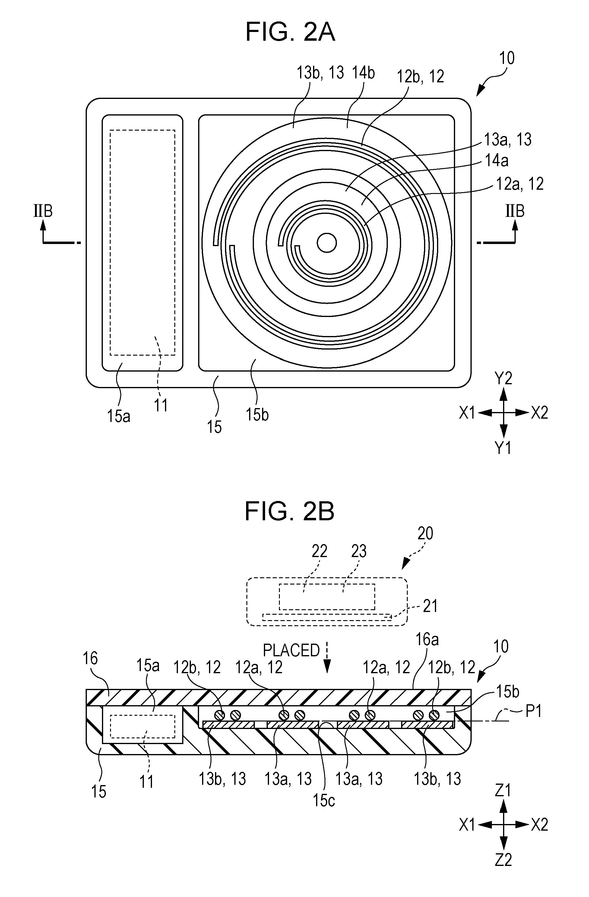
[0049]Throughout the foregoing description, it is assumed that, in each drawing, an X1 direction is a left direction, an X2 direction is a right direction, a Y1 direction is an anterior direction, a Y2 direction is a posterior direction, a Z1 direction is an upper direction, and a Z2 direction is a lower direction and an explanation will be made.

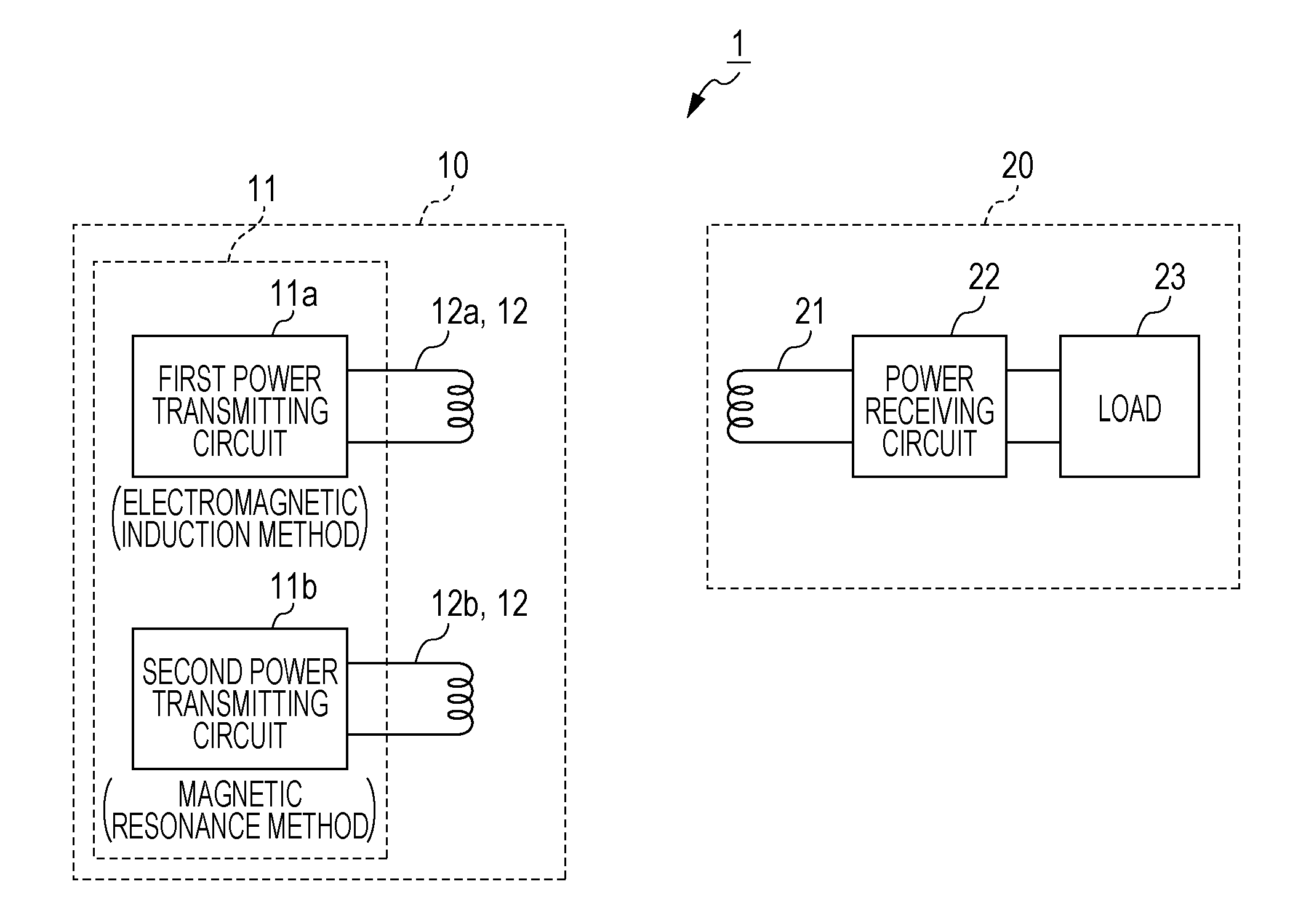
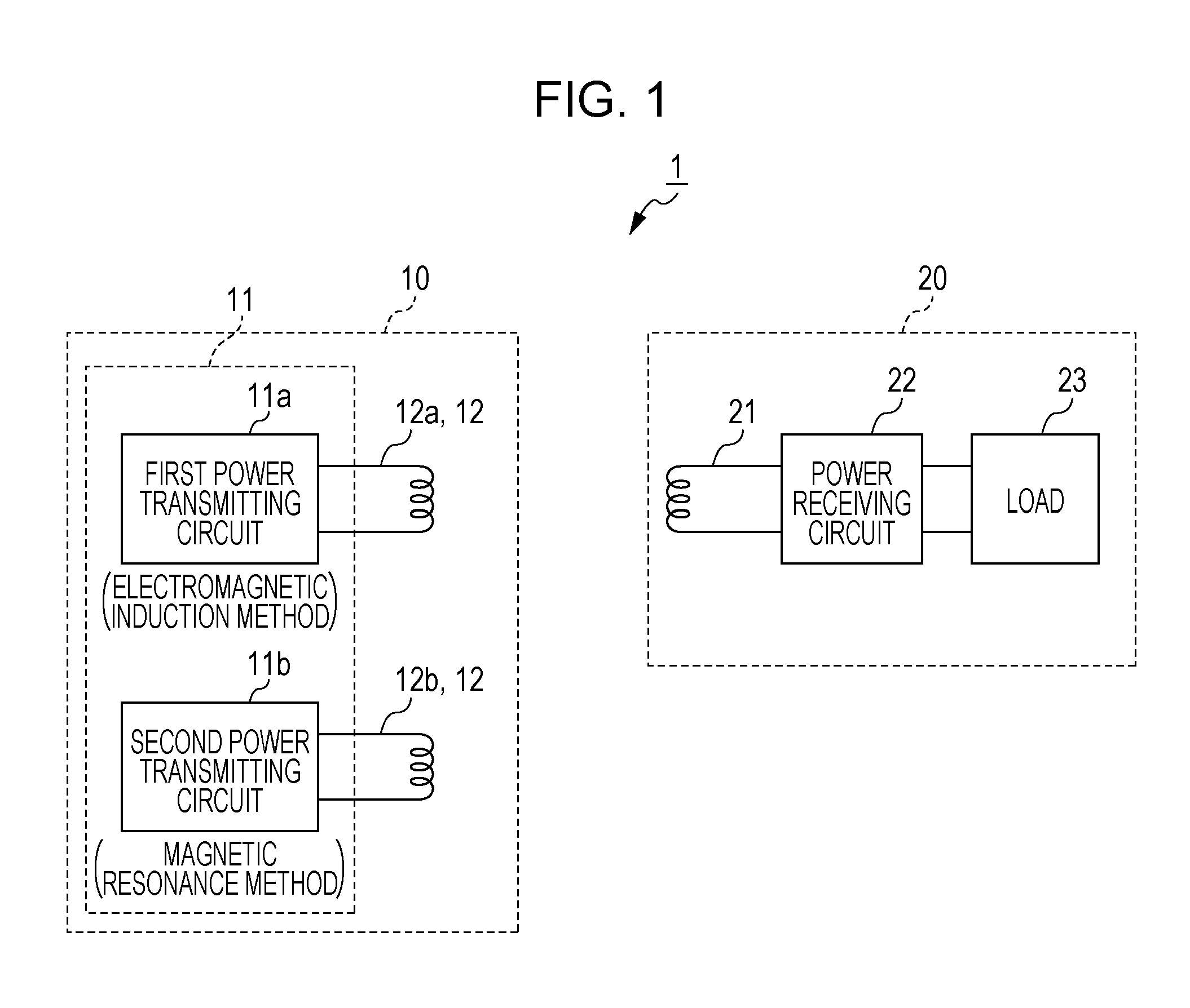
[0050]FIGS. 1 throu...


PUM


Abstract

A wireless power transmission system for wirelessly transmitting electric power from a power transmitting device to a power receiving device using magnetic field coupling between a power transmitting coil and a power receiving coil is provided. The power transmitting device includes a power transmitting circuit generating an electric signal for transmitting electric power, first and second power transmitting coils compatible with first and second transmission methods, respectively, a first magnetic substance on which the first power transmitting coil is placed, a second magnetic substance on which the second power transmitting coil is placed, and a power feeding surface on which the power receiving device is to be placed. First and second attachment surfaces of the first and second magnetic substances, respectively, are located on the lower side of the power feeding surface and arranged on a same plane surface parallel to the power feeding surface.

Description

CLAIM OF PRIORITY[0001]This application contains subject matter related to and claims the benefit of Japanese Patent Application No. 2014-016541 filed on Jan. 31, 2014, the entire contents of which is incorporated herein by reference.BACKGROUND OF THE DISCLOSURE[0002]1. Field of the Disclosure[0003]Embodiments of the present disclosure relate to a wireless power transmission system, and in particular, relates to a wireless power transmission system compatible with a plurality of transmission methods.[0004]2. Description of the Related Art[0005]In recent years, a wireless power transmission system that wirelessly transmits electric power from a power transmitting device to a power receiving device using magnetic field coupling between a power transmitting coil and a power receiving coil has been put to practical use.[0006]As the transmission method for electric power (hereinafter, abbreviated as a transmission method), which utilizes the magnetic field coupling, an electromagnetic in...

Claims


Application Information

Patent Timeline
Patent Type & Authority Applications(United States)
IPC IPC(8): H02J17/00
CPCH02J17/00H01F38/14H01F27/36H02J50/12H01F27/366H02J50/10H02J50/70
Inventor SAMPEI, TAKESHITABATA, MASASHIYAMAMOTO, MASAKI
Owner ALPS ALPINE CO LTD
Why Eureka
Try Eureka