Ring core optical fiber having sunk refractive indexes

A technology of refractive index and refractive index distribution, which is applied in the field of optical communication, can solve problems such as the limitation of the transmission distance of the ring-core optical fiber, and achieve the effect of increasing the transmission distance of the optical fiber and suppressing coupling and attenuation

Active Publication Date: 2018-05-18
SUN YAT SEN UNIV
View PDF5 Cites 13 Cited by
  • Summary
  • Abstract
  • Description
  • Claims
  • Application Information

AI Technical Summary

Problems solved by technology

In order to avoid the crosstalk coupling between the mode groups, the multi-input multi-output

Method used


Image

  • Ring core optical fiber having sunk refractive indexes
  • Ring core optical fiber having sunk refractive indexes

Examples


Embodiment Construction

[0018] In order to make the technical means, creative features, goals and effects achieved by the present invention easy to understand, the following will further explain how the present invention is implemented in conjunction with the accompanying drawings and specific embodiments.

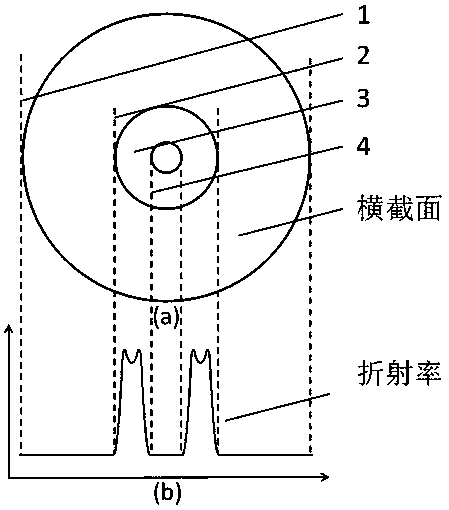
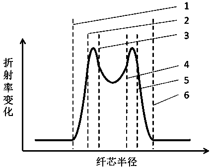
[0019] figure 1 (a) is a cross-sectional view of the fiber, figure 1 (b) is the refractive index distribution diagram on the cross-sectional diameter line, such as figure 1 As shown, the ring-core optical fiber provided by the present invention has a design with a concave refractive index distribution, wherein the refractive index distribution can be a graded refractive index distribution, which can be represented by 5 or more segmented curves, and each curve satisfies the gradient curve Formula, smooth transition between curves. figure 1 In , the auxiliary line 1 marks the outer interface of the fiber cladding, 2 marks the outer interface of the fiber core, 3 marks the symmetry center of the c...


PUM

PropertyMeasurementUnit
The inside diameter ofaaaaaaaaaa
Thicknessaaaaaaaaaa

Abstract

The invention relates to a ring core having sunk refractive indexes. Refractive index distribution of the ring core optical fiber from the outer side to the inner side has sunken areas. According to the invention, the ring core optical fiber has a design of refractive index distribution with sunken areas , so that coupling and attenuation of a module during a transmission process can be inhibitedeffectively and the optical fiber transmission distance can be increased further on the basis of not increasing system MIMO algorithm complexity.

Description

technical field [0001] The invention relates to the technical field of optical communication, and more particularly, to a ring-core optical fiber with a depressed refractive index. Background technique [0002] With the development of the Internet, people's requirements for communication capacity continue to increase. Due to the nonlinear effect of optical fiber and the influence of spontaneous radiation noise of optical amplifiers, the current commercial single-mode optical fiber communication system has encountered a bottleneck in its capacity growth and cannot meet the rapid growth of future communication capacity requirements. The mode-division multiplexing optical fiber communication system based on few-mode fiber can theoretically break the nonlinear Shannon limit of single-mode fiber, and has a high transmission capacity density, which has attracted extensive attention in recent years. However, with the expansion of system capacity and the increase of transmission di...

Claims


Application Information

Patent Timeline
IPC IPC(8): G02B6/028
CPCG02B6/0281
Inventor 刘洁朱国轩陈钰杰余思远
Owner SUN YAT SEN UNIV
Why Eureka
Try Eureka