

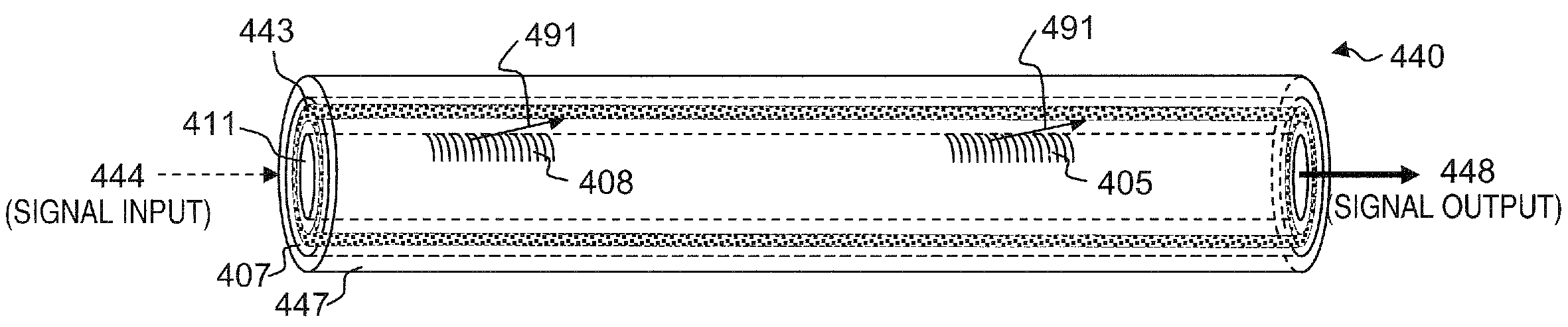
Apparatus and method for a high-gain double-clad amplifier
a double-clad amplifier, high-gain technology, applied in the field of optical waveguide manufacturing, can solve the problems of difficult removal using wavelength-selective filtering, undesirable signal light in the pump cladding, and noise or undesired bandwidth spreading of the desired signal, etc., to suppress instabilities, suppress certain instabilities and/or other undesirable effects, and effective
- Summary
- Abstract
- Description
- Claims
- Application Information
AI Technical Summary
Benefits of technology
Problems solved by technology
Method used
Image

Examples
Embodiment Construction
[0048]In the following detailed description of the preferred embodiments, reference is made to the accompanying drawings that form a part hereof, and in which are shown by way of illustration specific embodiments in which the invention may be practiced. It is understood that other embodiments may be utilized and structural changes may be made without departing from the scope of the present invention.
[0049]The leading digit(s) of reference numbers appearing in the Figures generally corresponds to the Figure number in which that component is first introduced, such that the same reference number is used throughout to refer to an identical component which appears in multiple Figures. Signals and connections may be referred to by the same reference number or label, and the actual meaning will be clear from its use in the context of the description.
[0050]As used herein, light, radiation, and electromagnetic radiation are equivalent terms and include any suitable wavelength of electromagne...
PUM
 Abstract
Description
Claims
Application Information