Method of producing large polymer optical blanks with predictable axil refractive index profile

a polymer optical and profile technology, applied in the field of large polymer optical blanks with predictable axil refractive index profiles, can solve the problems of severe neck injuries to pilots, high weight, and substantial contribution to the overall weight of headgear to which they are attached, and achieve accurate prescribing profiles. , the effect of short times

Inactive Publication Date: 2000-02-22
LIGHTPATH TECH INC
View PDF14 Cites 65 Cited by
  • Summary
  • Abstract
  • Description
  • Claims
  • Application Information

AI Technical Summary

Benefits of technology

In accordance with the present invention, a method and apparatus are provided that produce polymer gradient refractive index materials of large (macro) size, in relatively short times, with improved values of .DELTA.n, and with accurately prescribable profiles that can be tailored according to the design needs. The apparatus is used to form a blank comprising a plurality of polymer layers, the blank having a prescribed profile of index of refraction that varies continuously from a first surface to a second, opposite surface.

Problems solved by technology
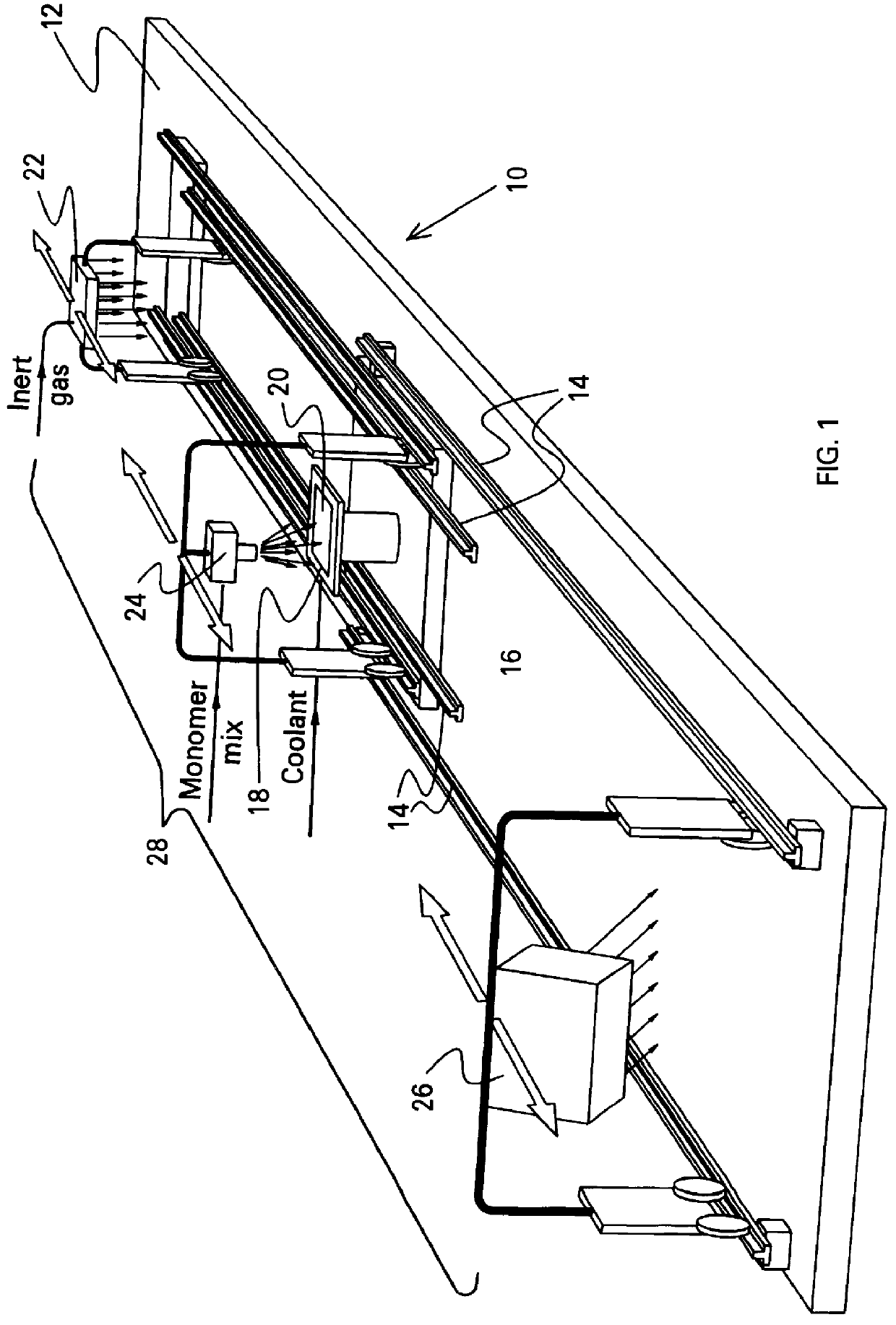
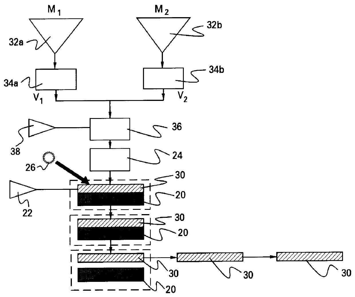
Another application involves night vision goggles, which comprise complex infrared optics mostly made of glass, which contributes substantially to the overall weight of the headgear to which they are attached.
In certain emergencies where a pilot wearing such a headgear has no time to remove it, the generated inertial forces can cause severe neck injuries to the pilot.
Finally, yet another application is prescription eye glasses, where the weight is highly undesirable, because heavy glasses are uncomfortable, tend to slide down, leave heavy marks on the skin, and dislodge more quickly in the case of an abrupt acceleration or deceleration.
However, these techniques suffer from one or more of the following disadvantages: (1) only small size optical elements, on the order of millimeters, can be produced; (2) a long time to fabricate optical elements is required; (3) only low .DELTA.n values, on the order of 0.02, are possible; and (4) no accurate prescribable tailoring of gradient profile is possible, thereby making available only specific profiles, as in the case of liquid-phase and vapor-phase diffusion techniques for thick and large samples; see, e.g., Yasukiro Koike et al, "Plastic axial gradient-index lens", Applied Optics, Vol. 24 (24), pp.

Method used


Image

  • Method of producing large polymer optical blanks with predictable axil refractive index profile
  • Method of producing large polymer optical blanks with predictable axil refractive index profile
  • Method of producing large polymer optical blanks with predictable axil refractive index profile

Examples


example 1

Monomer I: 85 parts by weight of styrene+15 wt. % dipentaerythritol pentacrylate (SR399--Sartomer Company)+0.5 parts by weight of benzoyl peroxide (thermal catalyst)+6.0 parts by weight of benzil dimethyl ketal (UV catalyst) (KB 1--Sartomer Company).

Monomer II: 85 parts by weight of glycidyl methacrylate (SR379--Sartomer Company)+15 parts by weight of dipentaerythritol pentacrylate (SR399--Sartomer Company)+0.5 parts by weight of benzoyl peroxide (thermal catalyst)+6.0 parts by weight of benzil dimethyl ketal (UV catalyst) (KB1--Sartomer Company).

example 2

Monomer I: 85 parts by weight of styrene+15 parts by weight of dipentaerythritol pentacrylate (SR399-Sartomer Company)+0.5 parts by weight of benzoyl peroxide (thermal catalyst)+6.0 parts by weight of benzil dimethyl ketal (UV catalyst) (KB1--Sartomer Company).

Monomer II: 100 parts by weight of tripropylene glycol diacrylate (SR306--Sartomer Company)+0.5 parts by weight of benzoyl peroxide (thermal catalyst)+6.0 parts by weight of benzil dimethyl ketal (UV catalyst) (KB1--Sartomer Company).

example 3

Monomer I: 85 parts by weight of styrene+15 parts by weight of dipentaerythritol pentacrylate (SR399--Sartomer Company)+0.5 parts by weight of benzoyl peroxide (thermal catalyst)+6.0 parts by weight of benzil dimethyl ketal (UV catalyst) (KB1--Sartomer Company).

Monomer II: 90 parts by weight of propoxylated neo-pentyl glycol diacrylate (SR9003--Sartomer Company)+10 parts by weight of dipentaerythritol pentacrylate (SR399--Sartomer Company)+0.5 parts by weight of benzoyl peroxide (thermal catalyst)+6.0 parts by weight of benzil dimethyl ketal (UV catalyst) (KB1--Sartomer Company).

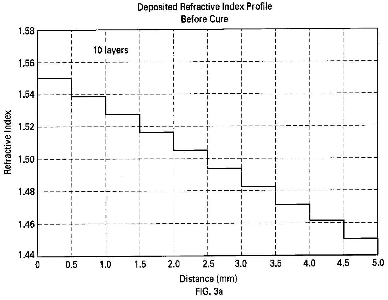
The Monomers have the index of refraction n and the viscosity as listed in Table II below. The calculated change in index of refraction .DELTA.n of the resulting polymer (based on the monomer values) is also listed. UV exposure is based on a UV source, model RC600 from Xenon Company, vertical directed 4 inches above the sample, where the UV intensity averaged at 365 nm is about 4 milliwatts per square centim...


PUM

PropertyMeasurementUnit
temperatureaaaaaaaaaa
refractive indexaaaaaaaaaa
wavelengthaaaaaaaaaa

Abstract

An apparatus and process are provided for depositing a polymeric element having a gradient in index of refraction that traverses the element from one surface to an opposite surface (axially graded refractive index). Two (or more) monomers are mixed in varying proportions and spray-deposited onto a substrate to form a layer. Each layer is then exposed to light to form a polymeric layer, and another layer deposited. Where the light is UV radiation and a light-sensitive catalyst that is also sensitive to the ambient atmosphere is used, then an inert gas dispenser, which provides an inert gas over the monomer layer, may be employed in conjunction with the UV radiation. Several layers are thus spray-deposited and exposed to light, each layer comprising a different mix of the two monomers, thereby providing each layer with a different index of refraction. After the prescribed number of layers has been deposited, the polymeric element is heat-treated to cause fusion of the layers and diffusion of components, thereby smoothing out the gradient profile. The apparatus and process of the invention are also useful in producing structural gradients in polymeric elements.

Description

The present invention relates generally to materials having a graded index of refraction, more particularly, to polymers having such a gradient, and, even more particularly, to a process and apparatus for fabricating such polymers accurately.Glass-based gradient refractive index (GRIN) materials, often called in the literature GRIN materials, have been studied for several years. Only in recent years, however, has this technology been brought to the market place with regard to large (e.g., at least 5 mm along the optical path), macrogradient (e.g., .DELTA.n greater than 0.085) lens blanks, under the trademark GRADIUM.RTM., by LightPath Technologies (Albuquerque, N.Mex.).Glass-based gradient refractive index materials find a wide variety of uses, including imaging lenses in optical systems, such as still and video cameras, copying machines, binoculars, microscopes, endoscopes, etc., as non-imaging lenses in concentrators, such as solar concentrators, collimators, such as laser collima...

Claims


Application Information

Patent Timeline
Patent Type & Authority Patents(United States)
IPC IPC(8): B29B11/14B29B11/00B29B11/06B29D11/00G02B3/00B29C35/08
CPCB29B11/06B29B11/14B29D11/00G02B3/0087B29C2035/0827B29C2791/001B29K2995/0031B29C49/071B29C2949/0715
Inventor WEITZEL, WILLIAM H.ORTABASI, UGUR
Owner LIGHTPATH TECH INC
Why Eureka
Try Eureka