Polarisation asymmetric active optical waveguide, method of its production, and its uses

a technology of polarisation mode and active optical waveguide, which is applied in the shape and construction of active medium, instruments, lasers, etc., can solve the problems of limiting the use of optical communication applications of power exchange between two polarisation modes, and introducing the risk of fiber breakage, so as to enhance the photosensitivity of the waveguide materials, enhance the refractive index, and enhance the effect of photosensitivity

Inactive Publication Date: 2000-11-21
KOHERAS +1
View PDF5 Cites 63 Cited by
  • Summary
  • Abstract
  • Description
  • Claims
  • Application Information

AI Technical Summary

Benefits of technology

According to the invention, at least a part of the active optical waveguide is exposed to an effective transverse illumination of light which light is able to react with the photorefractive dopant and to modify the transverse refractive index profile.
Suitable photorefractive dopants and illumination lights are known in the art.
According to the invention, the active optical waveguide is being exposed to a fluence of the illumination light which is able to provide selective suppression of the propagation of the light guiding modes having different polarisations to such an extent that the propagation of light in one mode is less suppressed than the propagation of light in the other mode(s).
In practice the skilled person is able to decide when a sufficient fluence has been obtained by simply measuring the light propagation of the active optical waveguide, e.g. by means of a fiber polarisation controller, a polarizer and a power meter; or a high-Q Fabry-Perot interferometer in which different modes can be resolved, and then decide when a measured polarisation asymmetry is sufficient for the intended application, e.g. to be used in a polarisation single mode fiber optical FDB or DBR laser.
In this embodiment, the dopant typically has a double function of both affecting, e.g. raising, the refractive index and enhancing the photosensitivity of the waveguide materials, e.g. Ge both increases the refractive index and enhances the photosensitivity. In particular, fewer steps in the manufacturing process are required when the transverse refractive index profile and the transverse photorefractive dopant profile are established by a double-functioning dopant and if no other dopants are used that affect either the refractive index or the photosensitivity of the waveguide material.
In particular germanium (Ge) is known to both raise the refractive index and enhance the photosensitivity of glass.

Problems solved by technology

However, power exchanges between two polarisation modes limit their use in optical communication applications because of instabilities in the laser output power implied by this power exchange between the modes and e.g. temperature and vibration sensitivity of the laser cavities.
The manufacture of the twisted optical fiber includes a mechanical twist of the fiber which is difficult to control and which introduces the risk of breaking the fiber.

Method used


Image

  • Polarisation asymmetric active optical waveguide, method of its production, and its uses
  • Polarisation asymmetric active optical waveguide, method of its production, and its uses
  • Polarisation asymmetric active optical waveguide, method of its production, and its uses

Examples


example 1

Polarisation Asymmetric Active Optical Fiber

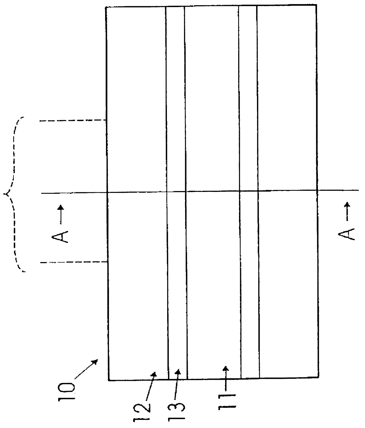
An example of an embodiment of an active optical waveguide having asymmetric polarisation according to the invention was produced in the following way. An optical fiber with a transverse refractive index profile and transverse photorefractive dopant profile as shown in FIGS. 4A and 3B, respectively, was provided (lot no. 930810, Lucent Technologies Denmark A / S (former Lycom A / S), Brondby, Denmark). 5 cm of this optical fiber was placed in a groove and illuminated at 248 nm using a KrF excimer laser. The fiber was illuminated with a total fluence of about 1.2 kJ / cm.sup.2. When illuminated under the same conditions but through a 5 cm long phase mask, Bragg gratings were photoinduced with a peak reflectivity of 99%. Polarisation asymmetry was proved by employing such a fiber in a DFB laser configuration, where further the central portion of the illuminated section was illuminated separately to induce a .pi. / 2 phase shift as required for DFB l...

example 2

DFB Optical Fiber Laser

In this experiment a 5 cm of Er.sup.34 :Ge:Al codoped silica fiber (lot no. 930810 supplied by Lucent Technologies Denmark A / S (former Lycom A / S), Brondby, Denmark) was spliced to standard fiber pigtails equipped with angled connectors.

Bragg gratings were photoinduced using a KrF excimer laser illuminating the fiber with 248 nm light through a 5 cm long phasemask having 1071 nm spacing and zero-order suppression better than 5% (lot no. 6035Y-7-1071-50-3 supplied by QPS, Canada). The induced grating was 4.6 cm long and has a peak reflectivity of 99% of 1555.6 nm. A phase shift was induced in the central part of the grating by additional UV-exposure. The grating was pumped by a semiconductor laser giving 60 mW output around 1475 nm as shown in FIG. 6A.

The lasing was monitored using an optical spectrum analyzer. A scanning Fabry Perot interferometer was used to verify single mode operation. Single mode operation without mode hopping was observed continuously from...

example 3

Five Wavelength DFB Optical Fiber Laser

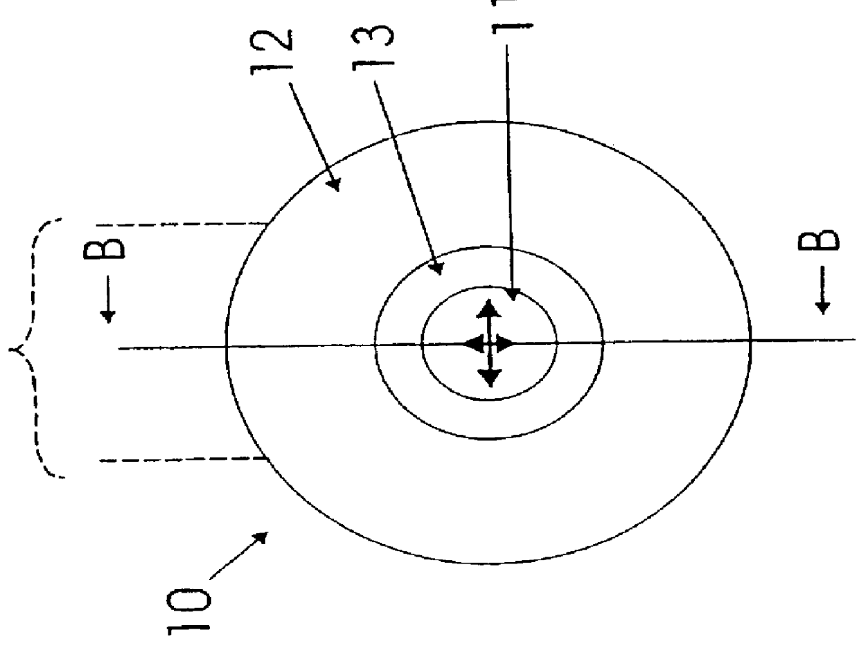
Each laser 52 (see FIG. 6B) was fabricated individually using 5 cm erbium doped fiber (lot no. 930810, supplied by Lucent Technologies Denmark A / S (former Lycom A / S), Br.o slashed.ndby, Denmark) spliced to dispersion shifted fibers and equipped with standard pigtails using angled connectors 62. The erbium doped fiber has a core, a cladding and an intermediate region and a dopant concentration of 1.5.times.10.sup.25 atoms m.sup.-3 in the core which has a diameter of 4 .mu.m and a numerical aperture of 0.27. The fiber has a photorefractive dopant profile comprising germanium in the intermediate region. The Bragg gratings and polarisation asymmetry are photoinduced simultaneously using a KrF excimer laser with 284 nm light illuminating a 5 cm long phasemask having 1071 nm spacing and zero-order suppression better than 5% (lot no. 6035Y-7-1071-50-3 supplied by QPS, Canada).

The fluence on the fiber is around 0.4 J / cm.sup.2 per pulse. After around 30...


PUM


Abstract

A method of producing an active optical waveguide having asymmetric polarization, said method comprising the steps of (a) providing an active optical waveguide (10) comprising: (i) a transverse refractive index profile (21) comprising a guiding region (11), an intermediate region (13), and a non-guiding region (12); (ii) a transverse photorefractive dopant profile (31) comprising a constant or graded photorefractive dopant concentration within at least one of the guiding, non-guiding and intermediate regions, except that the photorefractive dopant is not located solely in the guiding region; and (iii) exhibiting in said guiding region, intermediate region, or both, light guiding modes having different polarizations; and (b) exposing at least a part (10a, 10b) of the active optical waveguide to an effective transverse illumination of light (20) reacting with the photorefractive dopant and modifying said transverse refractive index profile; said part of the active optical waveguide being exposed to a fluence selectively suppressing the propagation of the light guiding modes having different polarizations so that the propagation of one mode is less suppressed than the propagation of the other mode(s). Such an active optical waveguide, single polarization mode optical waveguide lasers and multi-wavelength single polarization mode optical waveguide lasers comprising such an active optical waveguide, methods of their production, and their uses in telecommunications, in spectroscopy, in sensors and in absolute calibrated laser light sources.

Description

1. BACKGROUND OF THE INVENTIONThe present invention relates to a method of producing a polarisation asymmetric active optical waveguide, a polarisation asymmetric active optical waveguide obtainable by the method; a method of producing a single polarisation mode optical waveguide laser having a pump light source and distributed feedback or distributed Bragg reflector, a single polarisation mode optical waveguide laser having a pump light source and distributed feedback or distributed Bragg reflector obtainable by the method; in particular a multi-wavelength single polarisation mode optical waveguide laser having a pump light source and distributed feedback or distributed Bragg reflector; and uses of such a polarisation asymmetric active optical waveguide and single polarisation mode optical waveguide lasers, in particular in telecommunication networks, in spectroscopy, in sensors, and in absolute calibrated laser light source.The Technical FieldActive optical waveguides doped with a...

Claims


Application Information

Patent Timeline
Patent Type & Authority Patents(United States)
IPC IPC(8): G02B6/10H01S3/067H01S3/06H01S3/08
CPCG02B6/02109G02B6/02119G02B6/03627G02B6/105H01S3/06708G02B6/03633G02B6/02138H01S3/0675H01S3/06712H01S3/06729
Inventor KRISTENSEN, MARTINHUBNER, JORGVARMING, POULSEJKA, MILANPALSDOTTIR, BERA
Owner KOHERAS
Why Eureka
Try Eureka