
Contactless data communications coupling

a high-speed data and communication technology, applied in the direction of railway signalling, signalling indicators on vehicles, transportation and packaging, etc., can solve the problems of limiting the ability to achieve such high-speed data rate transfer, coarse pin connections are also subject to electrical radiation and interference, and electrical couplings are limited to conveying electrical power or low-bandwidth data signals of less than one megabit per second, etc., to achieve the effect of convenient mounting

Inactive Publication Date: 2010-02-25
KINKISHARYO INT
View PDF10 Cites 21 Cited by
  • Summary
  • Abstract
  • Description
  • Claims
  • Application Information

AI Technical Summary

Benefits of technology

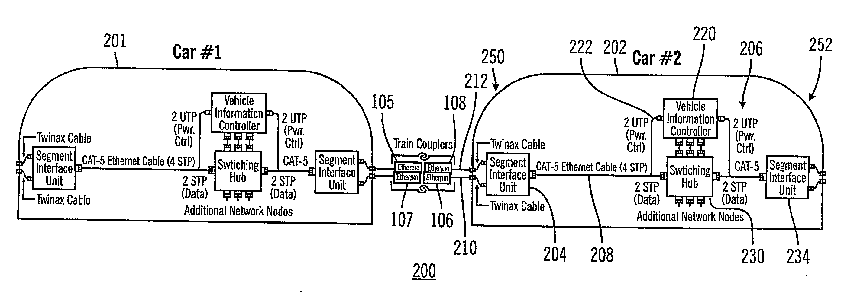
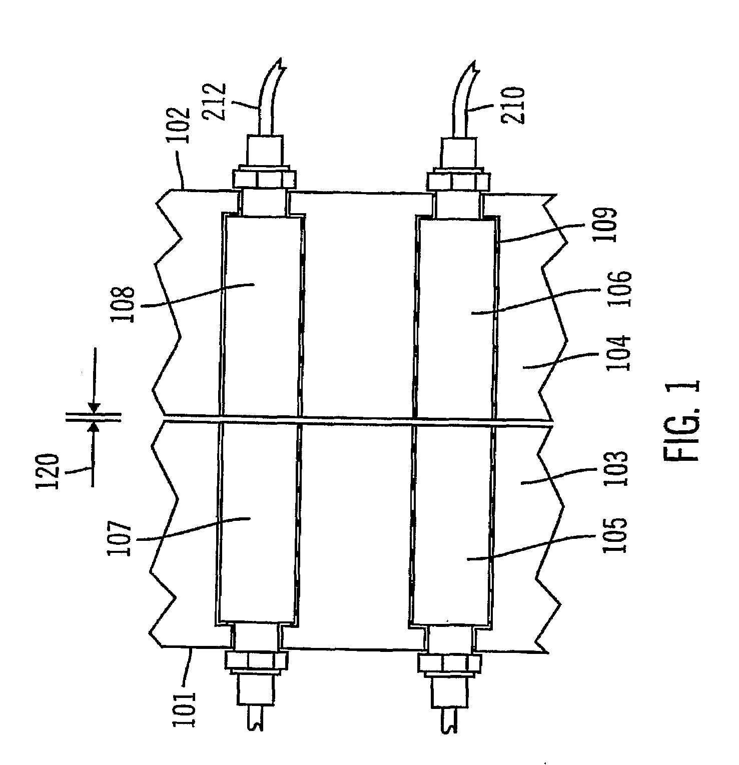
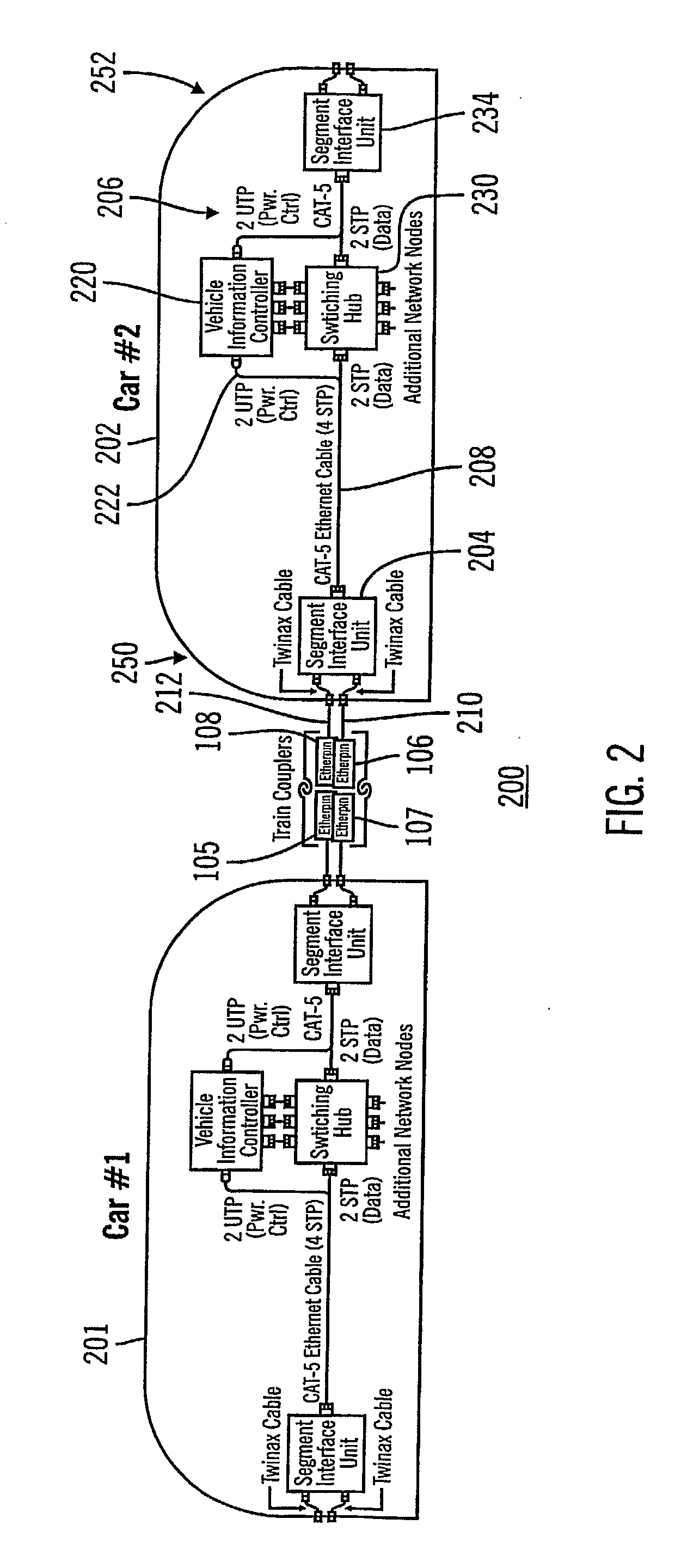
[0008]The exemplary embodiments of the present invention provide a non-contact data connection that is adaptable to use in a mechanical rail car coupler environment using conventional electrical coupler heads. These embodiments utilize a primarily magnetic field coupling to communicate either baseband data or RF signals through a quick-disconnect electrical coupling device that can be easily mounted in an electrical coupler head.

Problems solved by technology

Without intensive signal conditioning, such electrical couplings are limited to conveying electrical power or low bandwidth data signals of less than one megabit per second because of a large difference between the impedance of high-speed data cable and the impedance of the pins and of the junction between the pins.
Such coarse pin connections are also subject to electrical radiation and interference due to the large spacings between adjacent pins of a head.
The physical size, structure and environment of railroad couplers generally limit the ability to achieve such high data rate transfers through quick-disconnect pin couplings.
Conventional RF communication, however, is subject to interference and cross-talk between different consists because of the use of a common carrier frequency (e.g., 2.4-GHz in the case of 802.11g), especially when conventional antenna systems are used.

Method used


Image

  • Contactless data communications coupling
  • Contactless data communications coupling
  • Contactless data communications coupling

Examples


Embodiment Construction

[0018]Exemplary embodiments of the present invention utilize one of two different approaches for transferring high-speed data across two coupled cars using a signal coupling system that neither requires nor uses ohmic contact between the cars. Each approach is able to carry, for example, 100-Mbit / sec Ethernet signals from one car to another across signal coupling units that are easily incorporated into a head of a mechanical train coupler. The first of these approaches directly couples the Ethernet baseband signal through custom-designed magnetics within each signal coupling unit that are used in combination with specialized active signal conditioning circuitry of the system. This approach is capable of full-duplex Ethernet communication at 100-Mbits / sec. The second of these approaches incorporates an intermediate conversion to a radio frequency (RF) signal, such as an IEEE 802.11a wireless format, that operates in the vicinity of 5-GHz. The RF signal is transmitted across the signa...


PUM


Abstract

The exemplary embodiments of the present invention provide a high-speed contactless data coupling that is adaptable to use with mechanical rail car couplers. The exemplary embodiments utilize a primarily magnetic field coupling to communicate either baseband data or RF signals through a pair of signal coupling units that do not need to contact either other, which can be easily housed in two heads attached to each of two mechanical rail car couplers.

Description

RELATED APPLICATION[0001]The present application is related to and claims priority of a provisional application entitled CONTACTLESS DATA COMMUNICATIONS COUPLER IN A TRAIN COUPLING ENVIRONMENT METHOD AND SYSTEM, filed Jul. 7, 2005, and assigned Ser. No. 60 / 697,317, which application is assigned to the present assignee, and which application is hereby fully incorporated by reference herein.BACKGROUND OF THE INVENTION[0002]1. Field of the Invention[0003]This invention generally relates to the field of contactless high-speed data signal coupling and more specifically to the field of contactless high-speed data signal coupling systems and devices optimized for a train coupler environment.[0004]2. Description of the Related Art[0005]Railroad cars, including trams, streetcars and light rail cars (hereinafter “cars”), are generally connected together by mechanical couplers. An electrical coupler head (hereinafter “head”), which comprises a box-like electrical insulator, is mounted to each ...

Claims


Application Information

Patent Timeline
IPC IPC(8): B61G5/00
CPCB61G5/10H04B5/0093B61L15/0036H04B5/266
Inventor MARVEL, DENNIS K.KRUPPA, JURGEN
Owner KINKISHARYO INT
Learn More