Radio frequency warning system for ferromagnetic threats

a radio frequency warning and ferromagnetic technology, applied in the direction of electric signalling details, instruments, transportation and packaging, etc., can solve the problems of mri patients being potentially lethal, mri instruments being damaged, and pipe wrenches posing a threat of great harm to patients undergoing mri, and causing the death of patients

Inactive Publication Date: 2007-12-27
MEDNOVUS
View PDF8 Cites 14 Cited by
  • Summary
  • Abstract
  • Description
  • Claims
  • Application Information

AI Technical Summary

Benefits of technology

[0013]In an alternative third embodiment, the master module transmits on a first frequency and listens on a second frequency. The remote module transmits on the master module's listening frequency and listens on the master module's transmitting frequency. There is no need for a module gender ID. Gender identification for a module is accomplished by determining whether the module is transmitting on the first frequency or on the second frequency. In this third embodiment, either or both modules may alarm in a “signal strength” dual alarming mode.
[0014]In an alternative fourth embodiment, the master module transmits on one frequency and listens on a second frequency, a...

Problems solved by technology

Even small ferromagnetic objects that are inadvertently carried into a magnetic resonance imaging examination room can become potentially lethal projectiles in the very high field and high field gradient surrounding the MRI magnet.
Large ferromagnetic objects, such as oxygen tanks, floor scrubbers, tables, and pipe wrenches pose threat of great harm to p...

Method used


Image

  • Radio frequency warning system for ferromagnetic threats
  • Radio frequency warning system for ferromagnetic threats
  • Radio frequency warning system for ferromagnetic threats

Examples


second embodiment

[0074]In an alternative second embodiment of the invention, the threat warning system can operate using a one-way radio link, where the master module contains only a receiver and each of the remote modules contains only a transmitter. In this embodiment, the master module initiates an alarm if it receives a radio signal from a remote module that is above the predetermined threshold signal strength. This embodiment does not provide the redundancy described above for the preferred embodiment.

[0075]FIG. 10 shows a flow diagram of the functional system 200 of a typical remote module according to the aforementioned alternative second embodiment. This embodiment includes a Tx control 222, an encoder 232, a remote gender ID unit 247, a system ID unit 248, an RF transmitter 226, and an antenna 228.

[0076]The Tx control 222 initiates and controls the radio transmission. The period between transmissions is a pseudo-random time and is approximately one half second.

[0077]The encoder 232 formats ...

third embodiment

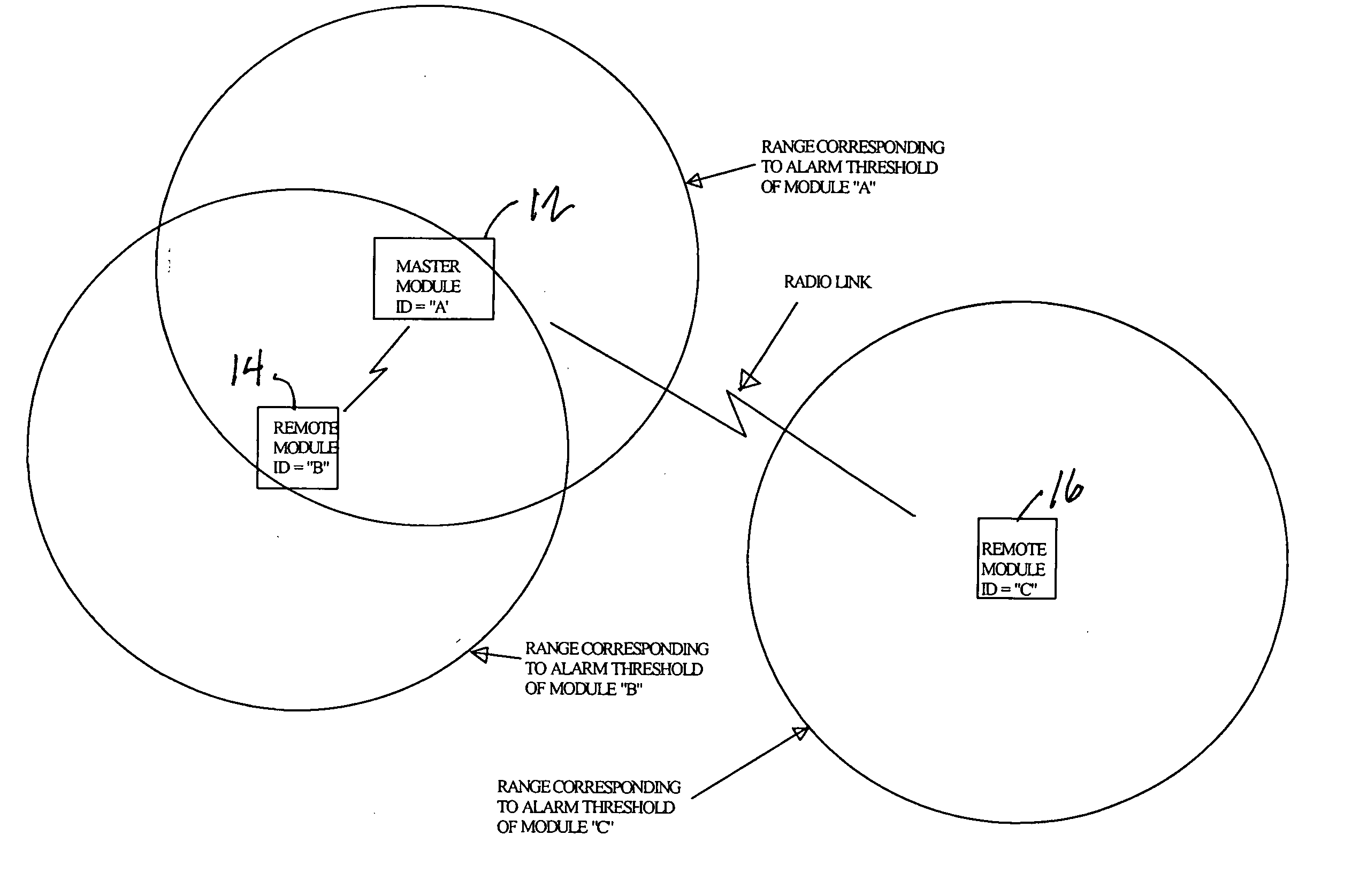
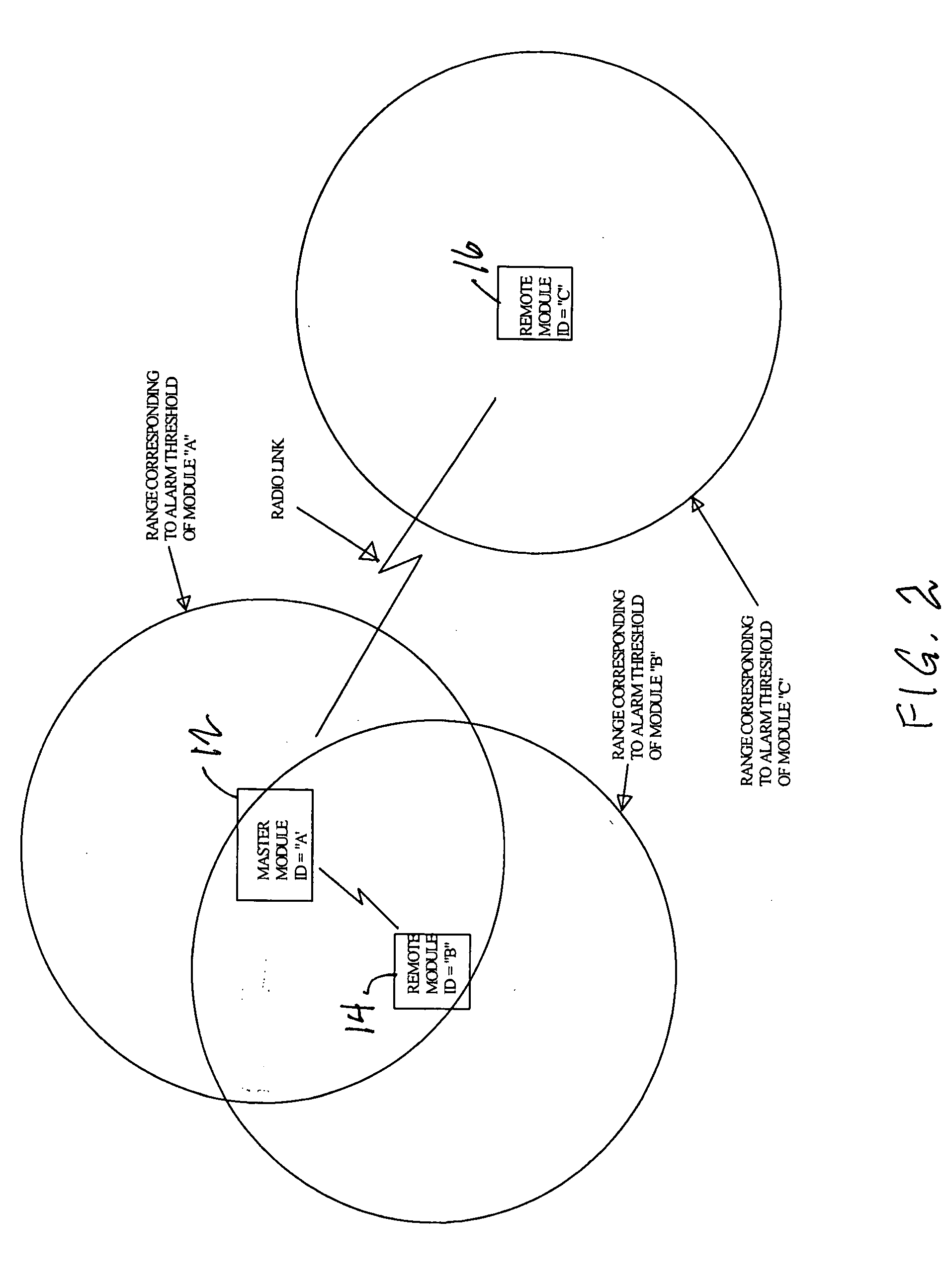
[0088]FIG. 12 illustrates the first means of initiating an alarm, via the signal strength, in an alternative If a radio signal is received from the same system identification, from an opposite gender of radio unit, and is above a pre-determined receive threshold, then a local alarm condition is activated at the receiving module. The circles represent the distance corresponding to a predetermined received signal strength at which an alarm is to be generated. A local alarm condition can result in activating the local visible and audible alarm outputs associated with the receiving module. In this embodiment, the master module 12′ transmits at a first frequency, denoted as “frequency 1”, and listens at a second frequency, denoted as “frequency 2”. Also, the remote modules 14′, 16′ transmit at frequency 2 and listen at frequency 1.

[0089]FIG. 13 shows a flow diagram of the functional system 700 of a typical remote module 14′, 16′ according to the alternative third embodiment. The Tx cont...

fourth embodiment

[0133]FIG. 18 shows basic radio message formats for the remote and master modules of the alternative fourth embodiment, which contains a synchronization pattern, a threat warning system ID field, an alarm status field, and a source ID field. In the signal from the remote unit to the master unit, the source ID field gives the unique identifier of the remote module transmitting the signal (the signal source ID), so that the master unit can identify any remote unit which approaches too close. In the signal from the master unit to the remote unit, the source ID field identifies any remote module which has approached too close and caused an alarm at the master module (the alarm source ID). If two or more master modules were to be used in a system in this embodiment, both the master module and the remote module would generate signals with both a signal source ID field and an alarm source ID field.


PUM


Abstract

A ferromagnetic threat warning system utilizing two or more radio frequency transmitters or transceivers. A remote transmitter or transceiver is attached to each ferromagnetic threat that may enter the area to be protected. A master receiver or transceiver is mounted at each door controlling entry into the area to be protected. Communication between any master unit and one or more remote units generates an alarm when one or more threat objects approaches within a preselected distance of any master unit. Approach of a threat object within the preselected distance from a door can be detected when the strength of a radio signal between the remote unit associated with the threat object and the master unit near the door reaches a predetermined level. Generation of an alarm can be initiated at either the affected remote unit or the affected master unit. Generation of an alarm at either the affected remote unit or the affected master unit can also result in generation of an alarm at the other of the two units.

Description

CROSS REFERENCE TO RELATED APPLICATIONS[0001]Not ApplicableSTATEMENT REGARDING FEDERALLY SPONSORED RESEARCH OR DEVELOPMENT[0002]Not ApplicableBACKGROUND OF THE INVENTION[0003]1. Field of the Invention[0004]This invention is in the field of methods and apparatus used in pre-screening to prevent entry of ferromagnetic threat objects into the vicinity of a magnetic resonance imaging (MRI) magnet.[0005]2. Background Art[0006]Even small ferromagnetic objects that are inadvertently carried into a magnetic resonance imaging examination room can become potentially lethal projectiles in the very high field and high field gradient surrounding the MRI magnet. Large ferromagnetic objects, such as oxygen tanks, floor scrubbers, tables, and pipe wrenches pose threat of great harm to patients undergoing MRI, as well as damage to the MRI instrument itself. Such objects are called “ferromagnetic threat objects” herein. A terrible accident occurred to a small boy when an oxygen tank was inadvertently...

Claims


Application Information

Patent Timeline
IPC IPC(8): G08B1/08G08B21/00
CPCG01R33/288G01R33/28
Inventor HOLOWICK, ERWIN
Owner MEDNOVUS
Why Eureka
Try Eureka