Touch sensitive keypad with tactile feedback

a tactile feedback and keypad technology, applied in the field of keys and keyboards, can solve the problems of high requirements on the size and weight aspect of electronic devices with a user interface, often faced with heavily contradictory requirements, and especially contradictory requirements

Active Publication Date: 2007-12-27
NOKIA TECHNOLOGLES OY
View PDF15 Cites 138 Cited by
  • Summary
  • Abstract
  • Description
  • Claims
  • Application Information

AI Technical Summary

Benefits of technology

[0007]On this background, it is an object of the present invention to provide a compact, design-and user friendly keypad. This object is achieved by providing a keypad for use with an electronic device, said keypad comprising a plurality of discrete keys formed by touch sensors or a plurality of virtual keys in a touch sensitive area, said plurality of discrete or virtual keys being mechanically coupled to a biased switch that is activated by pressing any of said discrete or virtual keys.

Problems solved by technology

Electronic devices with a user interface often face heavily contradicting requirements.
These requirements are especially contradicting for mobile devices which place extra high requirements on the size and weight aspect.
Increased complexity of mobile devices, such as mobile phones or smart phones have led to an increasing need for large displays.
Thus, additional space for the display can often only be obtained by allocating less space to the keypad.

Method used


Image

  • Touch sensitive keypad with tactile feedback
  • Touch sensitive keypad with tactile feedback
  • Touch sensitive keypad with tactile feedback

Examples


first embodiment

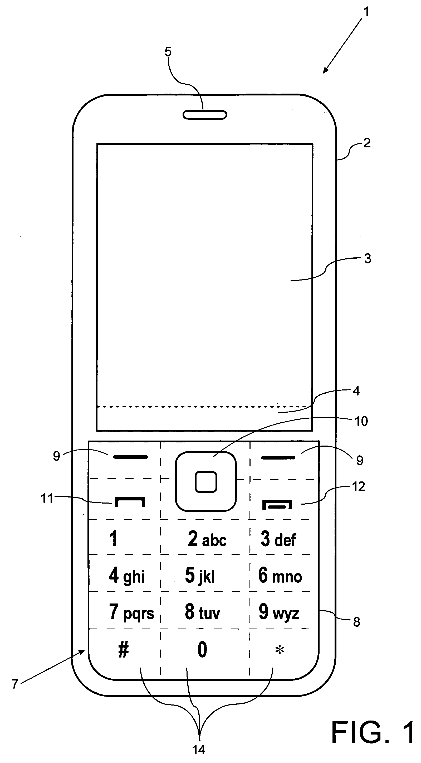
[0049]FIG. 1 illustrates a keypad according to the invention implemented in a mobile telephone by a front view. The mobile phone 1 comprises a user interface having a housing 2, a display 3, an on / off button (not shown), a speaker 5 (only the opening is shown), and a microphone 6 (not visible in FIG. 1). The phone 1 is adapted for communication via a cellular network, such as the GSM 900 / 1800 MHz network, but could just as well be adapted for use with a Code Division Multiple Access (CDMA) network, a 3G network, or a TCP / IP-based network to cover a possible VoIP-network (e.g. via WLAN, WIMAX or similar) or a mix of VoIP and Cellular such as UMA (Universal Mobile Access).

[0050]The keypad 7 has a first group of keys as alphanumeric keys, by means of which the user can enter a telephone number, write a text message (SMS), write a name (associated with the phone number), etc. Each of the twelve alphanumeric keys is provided with a figure “0-9” or a sign “#” or “*”, respectively. In alph...

second embodiment

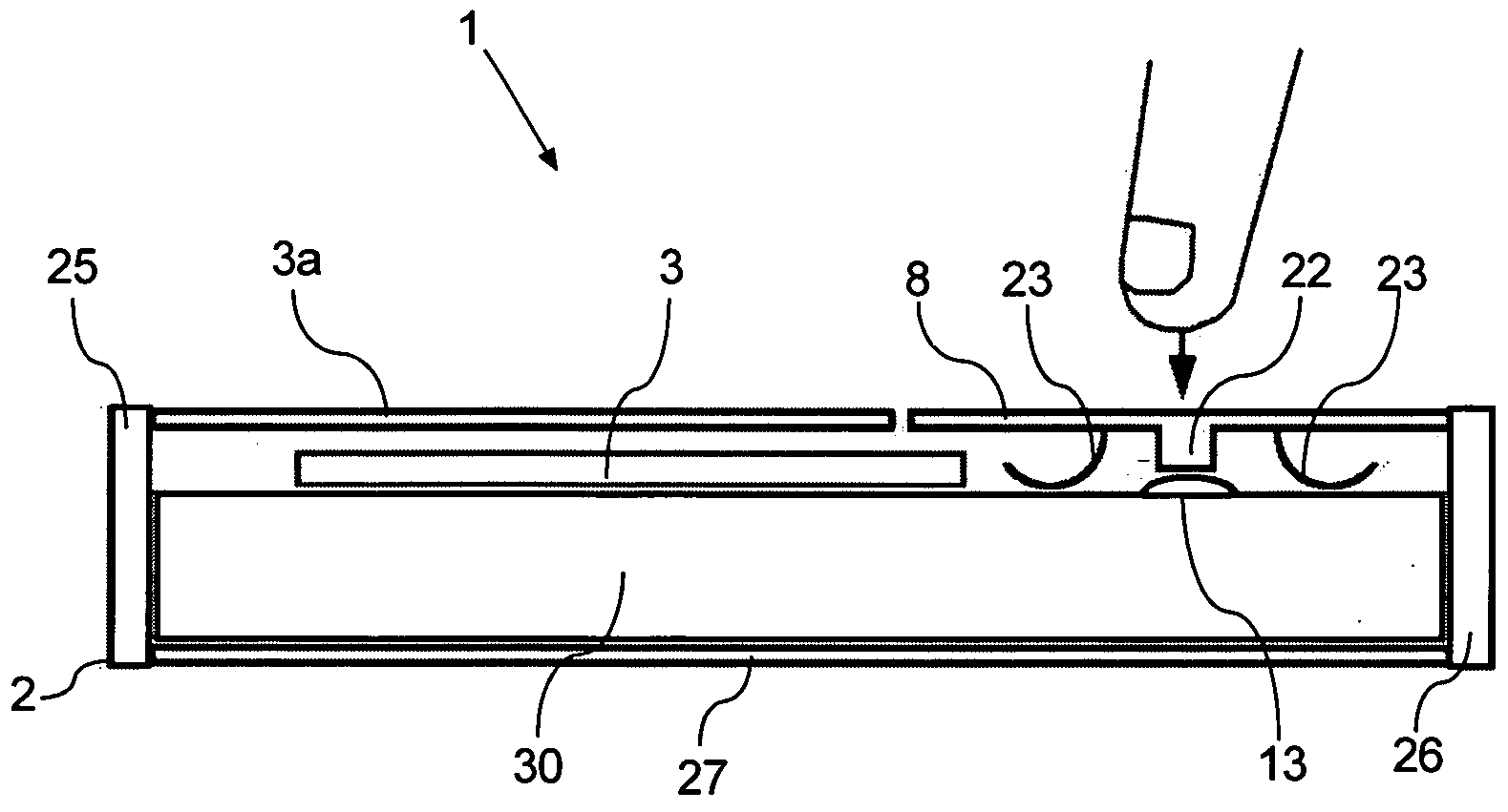
[0063]FIG. 9 shows the keypad 7 when it is depressed in a central position, e.g. when the user presses hard enough on the key marked “5”. When the plate member 8 is in this position an electrical contact is established (contacts not shown, but could be formed by the collapsible ring 33 in collaboration with a ring contact disposed on the printed circuit board 36).

[0064]FIG. 10 shows the keypad 7 according to the second embodiment when it is depressed in an off-center position, e.g. when the user presses hard enough on a key along the periphery of the keyboard. When the plate member 8 is in this position an electrical contact is established.

[0065]Thus, in the second embodiment the biased switch 13 is formed by the collapsible member 33 in combination with contacts.

[0066]The concept of a ring shaped collapsible member supporting a plate member is not limited to the combination with touch sensors, keypads or other user interface components on the plate member. Neither does the ring sh...

third embodiment

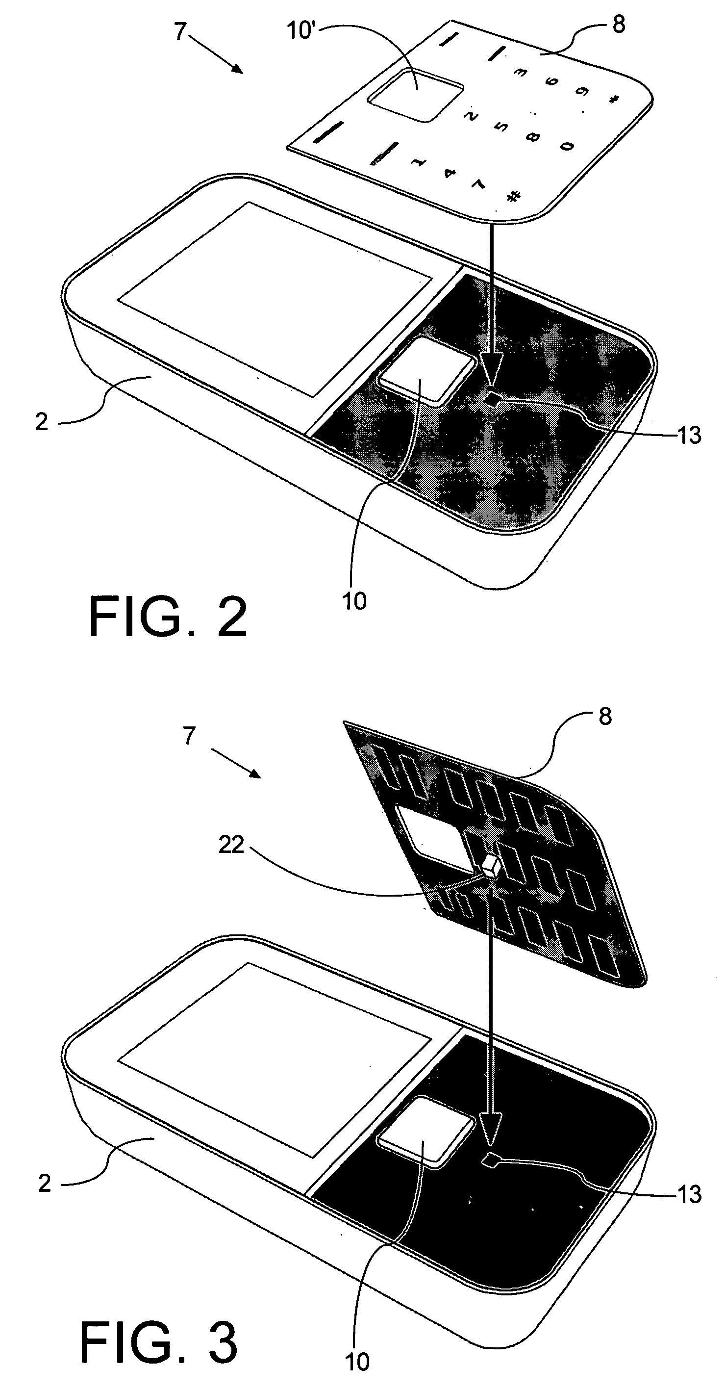
[0067]FIGS. 11 and 12 show the keypad 7 according to the invention. The keypad comprises a plurality of keys 44. A touch sensor 14 is placed on the top of each key 44. A slidable plate member 41 is disposed under the keys 44. The slidable plate member is suspended between two parallel guide rails 43 and can slide back and forth as indicated in the double headed arrow inFIG. 11. A biased switch 13 is arranged to face one of the edges of the plate member 41. The resilient characteristic of the biased switch urges the slidable plate member 41 to an idle or return to position.

[0068]The slidable plate member 41 includes a plurality of recesses or holes 42 that equals the number of keys 44. The recesses or holes 42 are provided with a slanting edge 48 that collaborates with a slanting surface 47 that is provided on a protrusion of 46 on the underside of the keys 44. The slidable plate member 41 is urged by the switch 13 to assume the position indicated in FIG. 12.

[0069]When one of the key...


PUM


Abstract

A keypad includes discrete keys formed by touch sensors or virtual keys on a touch sensitive area. The discrete or virtual keys are mechanically linked to a biased switch. The key that has been touched during a keystroke is identified through a signal from the touch sensors whilst a keystroke is recorded upon a signal from the biased switch. The combination of the touch sensors with a biased switch provides tactile feedback. The use of touch sensors or a touch sensitive area allows the keypad to be constructed with a substantially flush surface without parting lines.

Description

FIELD OF THE INVENTION[0001]The present invention relates to keypads and keyboards for electronic devices, in particular to keypads and keyboards that use touch sensors.BACKGROUND OF THE INVENTION[0002]Electronic devices with a user interface often face heavily contradicting requirements. On one hand the devices are required to be compact and light, whilst on the other hand the user interface should be user friendly and comfortable. These requirements are especially contradicting for mobile devices which place extra high requirements on the size and weight aspect. Increased complexity of mobile devices, such as mobile phones or smart phones have led to an increasing need for large displays. The “front” surface of the mobile device is typically completely occupied by the display and the keypad. Thus, additional space for the display can often only be obtained by allocating less space to the keypad.[0003]The display of a conventional mobile phone is typically a flat LCD color screen f...

Claims


Application Information

Patent Timeline
Patent Type & Authority Applications(United States)
IPC IPC(8): G09G5/00
CPCG06F1/1626G06F1/1662G06F1/169G06F3/0202G06F3/03547H04M2250/22H01H13/85H01H2215/01H01H2219/024H04M1/23G06F2203/04105G06F3/016
Inventor STRAWN, ANDREWBICK, ANDREW RAYMONDTOMPKIN, CRISPIANLEITH, DARENBRADFORD, SIMONMILES, LUKEDAVIDSON, BRIAN
Owner NOKIA TECHNOLOGLES OY
Why Eureka
Try Eureka