Optical fiber sensor and method

Inactive Publication Date: 2007-12-27
INSTITUT NATIONAL D'OPTIQUE
View PDF4 Cites 58 Cited by
  • Summary
  • Abstract
  • Description
  • Claims
  • Application Information

AI Technical Summary

Problems solved by technology

However, an orientation of the fiber must be considered in such decoupling, but this publication provides no detail as to how the fiber may be oriented in a desired manner.

Method used


Image

  • Optical fiber sensor and method
  • Optical fiber sensor and method
  • Optical fiber sensor and method

Examples


first embodiment

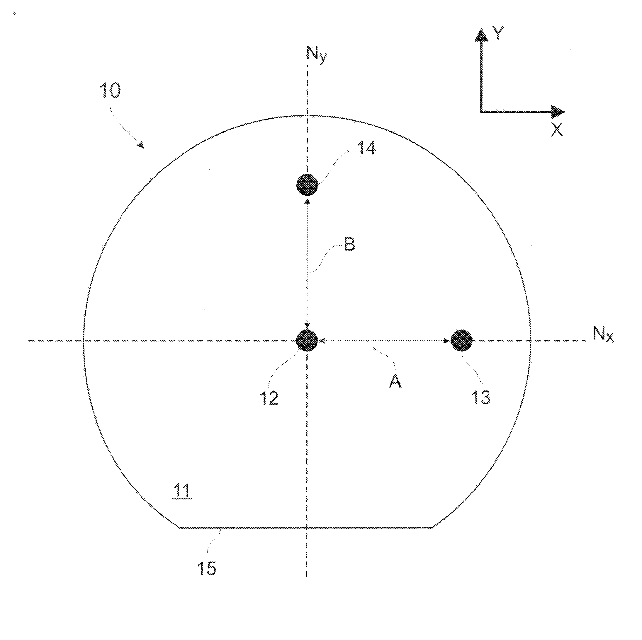
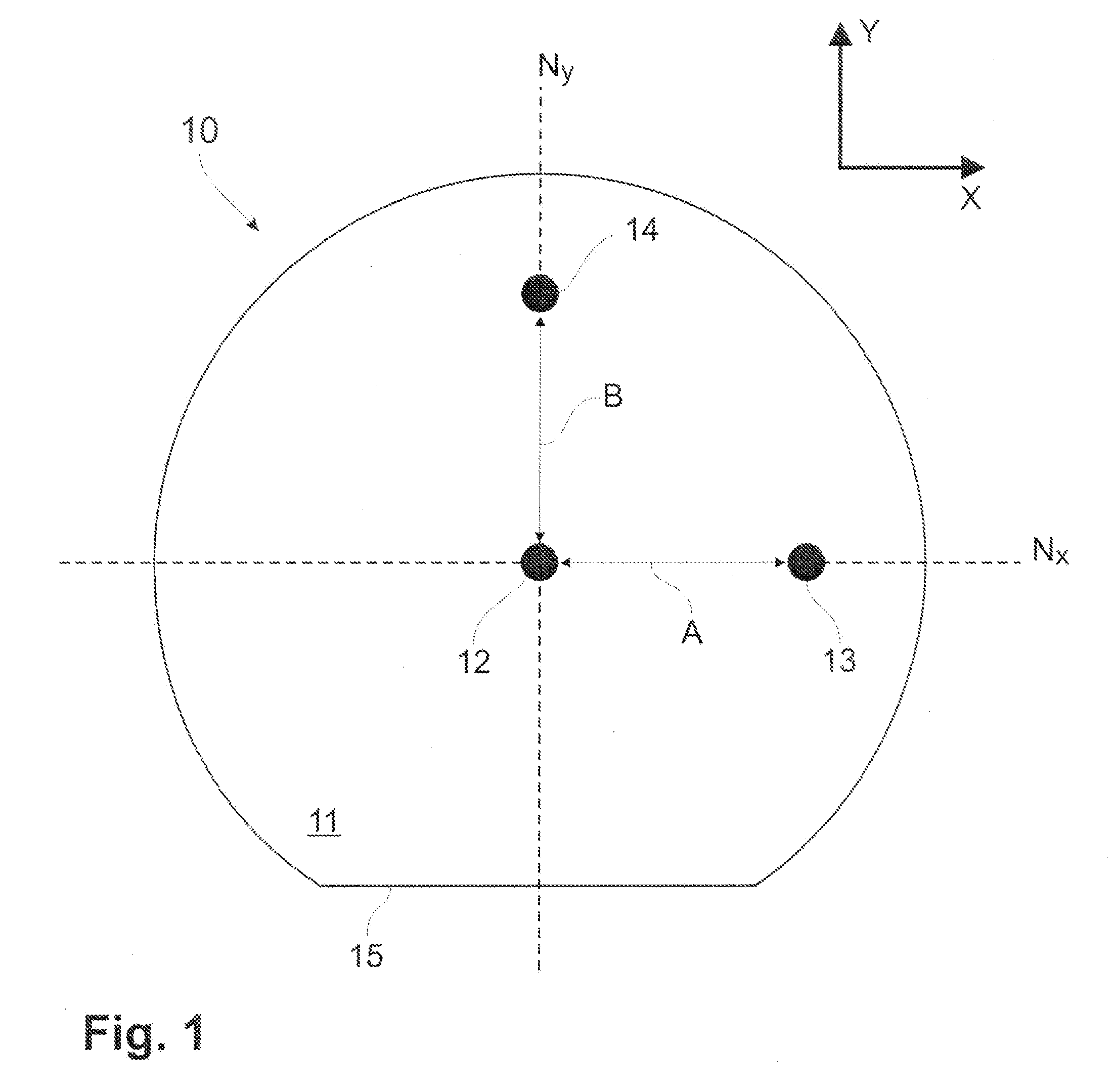
[0020]Referring now to the drawings and, more particularly, to FIG. 1, an optical fiber sensor in accordance with a first embodiment is generally shown at 10. The optical fiber sensor 10 is an optical fiber having a cladding 11, a central core 12, and peripheral cores 13 and 14.

[0021]The cladding 11 has a generally circular section, but has a flat edge, defining a flat surface 15 on the full length of the cladding 11. The cladding 11 is made of a material having an effective index of refraction smaller than that of the cores 12, 13 and 14.

[0022]The central core 12 is generally centrally positioned within the cladding 11, as is visible in FIG. 1.

[0023]The peripheral cores 13 and 14 are respectively spaced apart from the central core 12 by distances A and B. In the first embodiment of FIGS. 1 and 2, the central core 12 and the peripheral core 13 lie in a first neutral plane Nx generally parallel to the flat surface 15. The central core 12 and the peripheral core 14 lie in a second neu...

second embodiment

[0031]Referring to FIG. 4, an optical fiber sensor in accordance with a second embodiment is generally shown at 10′. The optical fiber sensor 10′ is generally similar to the optical fiber sensor 10 (FIG. 1), in that it has a cladding 11, a central core 12, and peripheral cores 13 and 14. The optical fiber sensor 10′ additionally has peripheral cores 13′ and 14′, diametrically opposed to the peripheral cores 13 and 14, respectively.

[0032]The peripheral cores 13′ and 14′ are provided to increase the sensitivity of the optical fiber sensor 10′. More specifically, the longitudinally aligned sets of gratings of the peripheral cores 13′ and 14′ are respectively combined with that of the peripheral cores 13 and 14, to provide two gratings per axis of curvature (e.g., axes X and Y of FIG. 1). For example, when the grating in the peripheral core 13 is compressed, the corresponding grating in the peripheral core 13′ is elongated, giving twice the total spectral shift, in opposite directions, ...

third embodiment

[0052]Referring to FIG. 7, an optical fiber sensor in accordance with a third embodiment is generally shown at 10″. The optical fiber sensor 10″ is similar to the optical fiber sensor 10′ of FIG. 4, whereby like reference numerals will designate like elements.

[0053]The cladding 11 of the optical fiber sensor 10″ has a generally circular section, but with a pair of flat edges, defining flat surfaces 15 and 15′ on the full length of the cladding 11. Advantageously, the fiber sensor 10″ is symmetrical along both the X- and Y-axes. The planes of symmetry are therefore coplanar with the first neutral plane Nx and the second neutral plane Ny. The presence of a pair of flat surfaces 15 and 15′ facilitates the securing of the optical fiber sensor 10″ in a desired orientation, and ensures that the central core 12 is n the neutral planes for both axes.

[0054]Amongst contemplated uses for the optical fiber sensors 10 / 10′ / 10″ and the optical fiber sensor system 100 are posture detection (e.g., h...


PUM


Abstract

An optical fiber sensor for detecting curvature of a body / structure comprises a cladding having an outer periphery. A central core receives and transmits light. The central core has Bragg gratings and is positioned in neutral planes of the cladding. Peripheral cores receive and transmit light. The peripheral cores have Bragg gratings and are peripherally positioned in the cladding with respect to the neutral planes. A connection configuration is provided in the outer periphery of the cladding to attach the optical fiber sensor to a body / structure such that the central core and the peripheral cores are in a predetermined orientation with respect to the body / structure to measure curvature of the body / structure.

Description

BACKGROUND OF THE INVENTION[0001]1. Field of the Invention[0002]The present invention relates to optical fibers and, more particularly, to optical fiber sensors to measure deformation.[0003]2. Background Art[0004]Optical fiber systems offering sensing functions have been used in numerous applications. One known sensor technology for optical fibers is the Bragg grating sensor. The Bragg grating is a periodic variation of the refractive index along the fiber axis and it is photoimprinted in the core of the fiber by using UV light. The main property of a Bragg grating is that part of the light going along the fiber is reflected back by the grating. This process is wavelength selective and the wavelength with the highest reflectivity is called the Bragg wavelength (typically located at the center of the spectral response). Any temperature variation or strain applied to the optical fiber might result in a Bragg wavelength shift and / or spectral deformation, depending on how perturbations ...

Claims


Application Information

Patent Timeline
Patent Type & Authority Applications(United States)
IPC IPC(8): G02B6/00
CPCG01B11/18G02B6/0208G02B6/02042
Inventor MENEGHINI, CHIARATHERIAULT, SYLVAINPARADIS, PATRICK
Owner INSTITUT NATIONAL D'OPTIQUE
Why Eureka
Try Eureka