Multistep diaphragm pump

a diaphragm pump and multi-step technology, applied in the field of pumps, can solve the problems of inability to bear high pressure satisfactorily, inconvenient to carry a larger load, and inability to function in a normal manner, etc., and achieve the effects of low noise, low volume and high transport efficiency

Inactive Publication Date: 2007-12-27
YANG ZHICHAO +2
View PDF10 Cites 16 Cited by
  • Summary
  • Abstract
  • Description
  • Claims
  • Application Information

AI Technical Summary

Benefits of technology

[0003]Considering the drawback of the pump in the prior art, it is an object of the present invention to provide a multistep diaphragm pump which has a small volume, high transport efficiency, low noise, long service life, and is easy to maintain.

Problems solved by technology

The existing diaphragm pump usually adopts a pneumatically driven diaphragm or a hydraulically driven diaphragm, and the diaphragm is usually a single-step diaphragm, such single-step diaphragm can not bear high pressure satisfactorily.
Once the diaphragm is damaged, the diaphragm can not function in a normal manner.
In addition, U.S. Pat. No. 4,049,366 disclosed a double-diaphragm pump; the disadvantage of the double-diaphragm is that it is not suitable for bearing a larger load.
In the situation where the crank lever mechanism is used, it results in a large volume, therefore, the space occupied by the equipment and the costs incurred are increased.
In the situation where a reset spring is used, the space occupied by the spring is small, however, the spring is prone to damage, therefore it need to be replaced quite often.

Method used


Image

  • Multistep diaphragm pump
  • Multistep diaphragm pump
  • Multistep diaphragm pump

Examples


Embodiment Construction

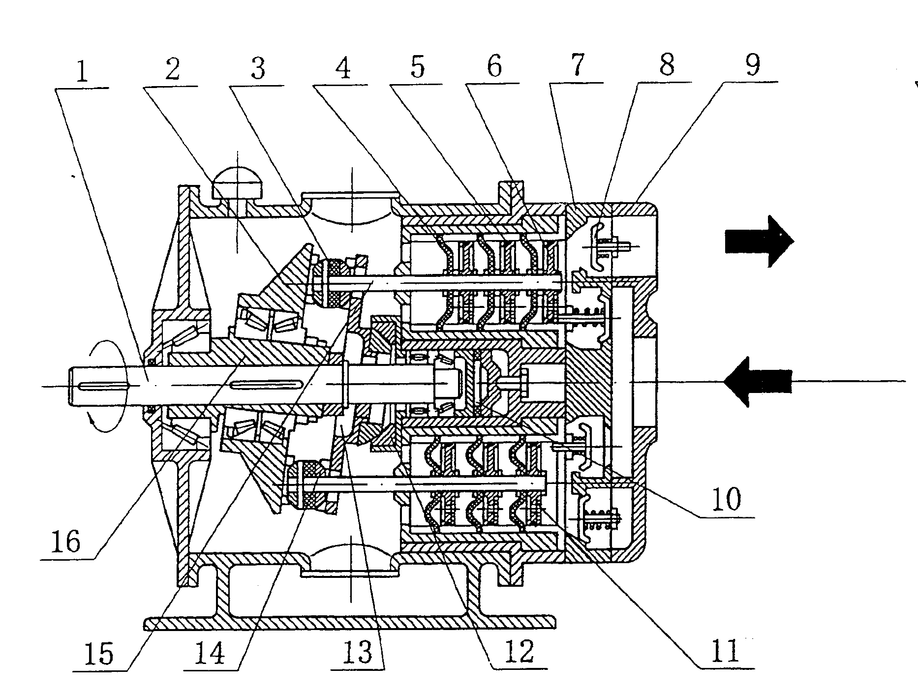
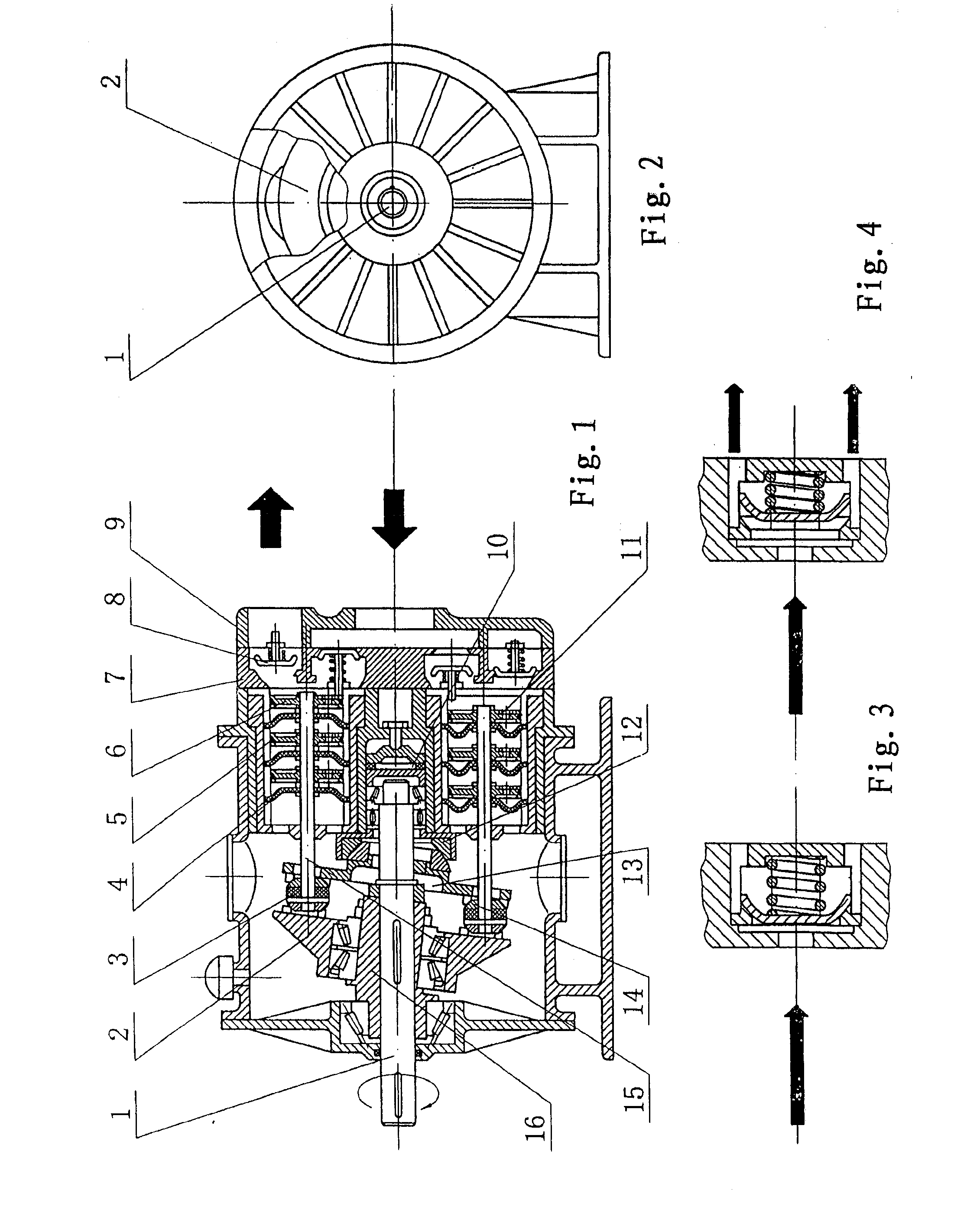
[0016]In the following description, the terms “front”, “rear” respectively refer to the “right side”, “left side” of the paper.

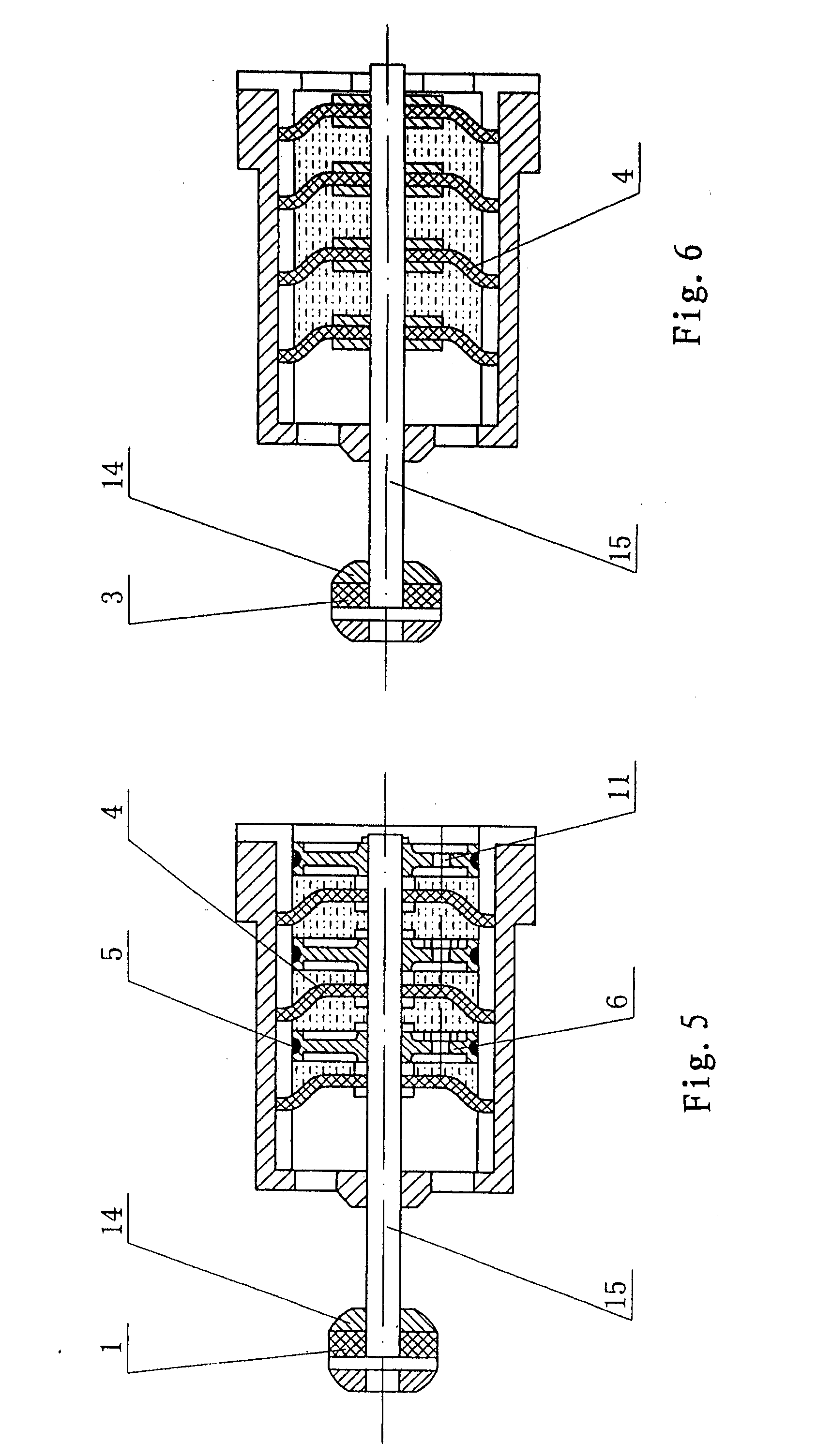
[0017]As shown in FIG. 1, the multistep diaphragm pump includes: a pump body; a main shaft 1; an eccentric shaft 16; a driving plate 2; several articulated bearings 14; a bridge board 13; a driving shaft 15, dish type diaphragms 4 and pistons 6 arranged in a working chamber; a valve plate 7; a pump cover 9. The eccentric shaft 16 is mounted on the main shaft 1, the driving plate 2 is mounted on the eccentric shaft 16 by means of a bearing; The main shaft 1, the eccentric shaft 16 and the driving plate 2 constitute a swing mechanism which is situated in the working chamber filled with lubricating oil. The articulated bearing 14 is arranged between the driving plate 2 and the bridge board 13. The bridge board 13 is mounted on the main shaft 1 by means of the central articulated bearing 12. The bridge board 13 is provided with a through hole at the central part...


PUM


Abstract

A multistep diaphragm pump comprising: a pump body; a main shaft; a reciprocated driving mechanism driven by the main shaft; a driving shaft connected with the reciprocated driving mechanism and extended into the working chamber of the pump body; on the relevant driving shaft there is provide a plurality of dish type diaphragms which are connected in series; in front of each dish type diaphragm there is fixed a piston having a sealing ring; between the adjacent two dish type diaphragms is filled with hydraulic medium, wherein the piston situated in the front of the most front dish type diaphragm directly contacts with the liquid material in the working chamber, a suction check valve and a discharge check valve are provided in the working chamber; the driving mechanism is constituted by the main shaft, the eccentric shaft, the driving plate, the articulated bearings and the bridge board, therefore the driving shaft can be moved reciprocally. The advantages of the pump is that the pump has small volume and compact structure; reasonable transmission, automatic clearance adjustment, noiseless property; high load pressure of the multistep diaphragm, high safe coefficient; the diaphragm and the piston protect each other in the sealing chamber, and there is no sealing, no leakage, and such pump has a long service life.

Description

TECHNICAL FIELD[0001]The present invention relates to a pump and in particular to a multistep diaphragm pump for transporting liquid material.BACKGROUND ART[0002]The existing diaphragm pump usually adopts a pneumatically driven diaphragm or a hydraulically driven diaphragm, and the diaphragm is usually a single-step diaphragm, such single-step diaphragm can not bear high pressure satisfactorily. Once the diaphragm is damaged, the diaphragm can not function in a normal manner. U.S. Pat. No. 3,809,506 disclosed such a single-step diaphragm pump. In addition, U.S. Pat. No. 4,049,366 disclosed a double-diaphragm pump; the disadvantage of the double-diaphragm is that it is not suitable for bearing a larger load. Furthermore, the driving mechanism for reciprocating the diaphragm usually adopts a crank lever mechanism or a cam-reset spring mechanism. In the situation where the crank lever mechanism is used, it results in a large volume, therefore, the space occupied by the equipment and th...

Claims


Application Information

Patent Timeline
Patent Type & Authority Applications(United States)
IPC IPC(8): F04B17/00F16J3/00
CPCF04B43/026F04B43/0054F04B43/02F04B53/02F04B53/10F04B53/14F04B53/16F05B2210/11F05B2240/57F05B2280/5001
Inventor WANG, MINGXIANLIU, SHENG
Owner YANG ZHICHAO
Why Eureka
Try Eureka