Connector and pushing jig

Inactive Publication Date: 2007-12-27
DDK LTD
View PDF4 Cites 6 Cited by
  • Summary
  • Abstract
  • Description
  • Claims
  • Application Information

AI Technical Summary

Benefits of technology

[0013] In view of the problems described above, it is an object of the invention to provide a connector enabling a reduced overall height or distance between two substrates, and achieving narrower pitches and stable connection even in the case of repeated connections, and further to provide a pushing jig for pushing the connector to mating objects.

Problems solved by technology

With the constructions disclosed in the Patent Literatures 2 to 4, however, as the contact portions adapted to contact mating objects are spiral, the contact portions become unavoidably larger so that narrower pitches cannot be achieved.
Due to the spiral shapes of the contact portions, moreover, the contact pressure is poor, with the result that stable connection cannot be realized.
Further, such spiral contact portions are not suitable for repeated contacts.

Method used


Image

  • Connector and pushing jig
  • Connector and pushing jig
  • Connector and pushing jig

Examples


Embodiment Construction

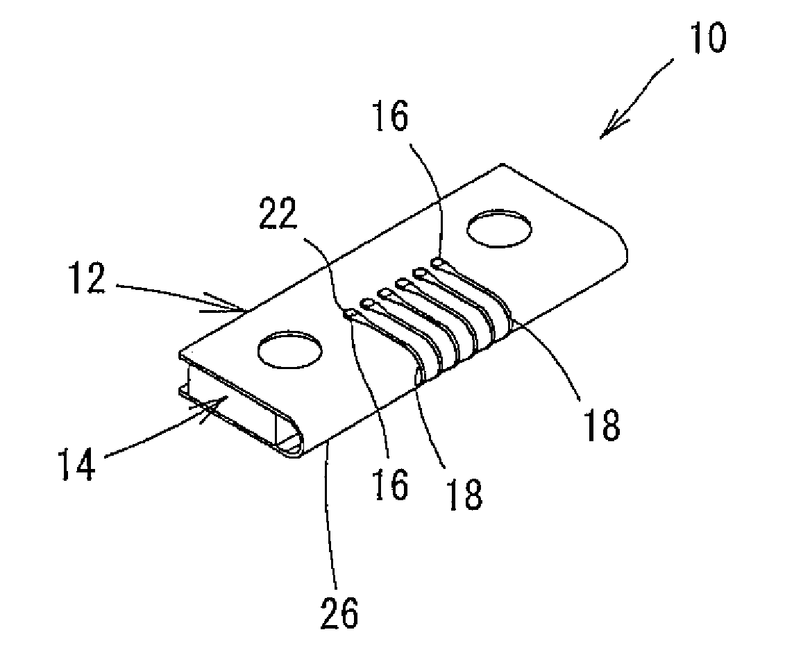
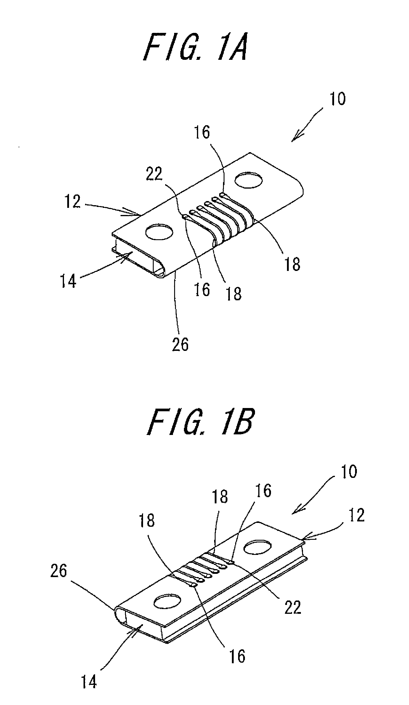
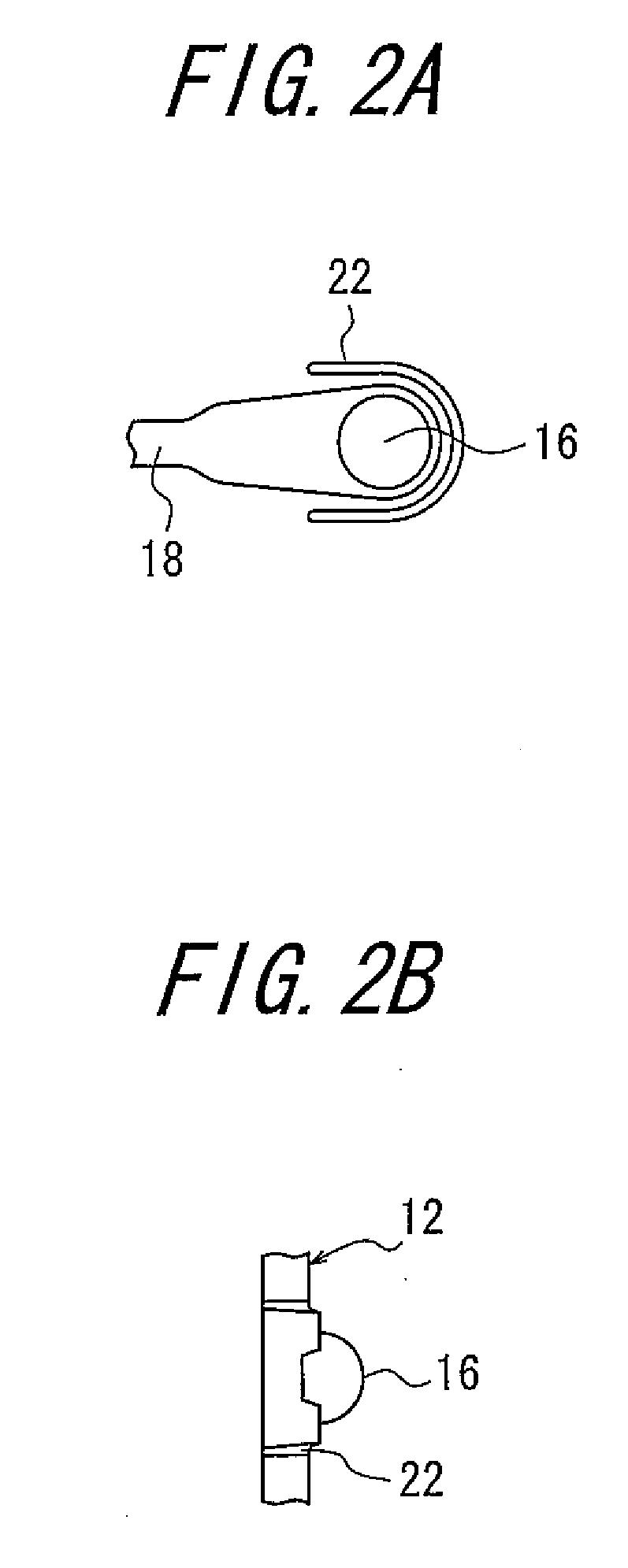
[0117] One embodiment of the connector according to the invention defined in claims 1 and 3 to 10 will be explained with reference to FIGS. 1A to 8. FIG. 1A is a perspective view of the connector folded back, viewed from the side of the fold line toward the front face, while FIG. 1B is a perspective view of the connector folded back, viewed from the opposite side of the fold line toward the rear face. FIG. 2A is a partly enlarged view of a contact portion, while FIG. 2B is a sectional view of the contact portion taken along its center. FIG. 3A is a plan view of a flexible printed circuit board having contact conductors arranged in a row viewed from contact portions, and FIG. 4A is a plan view of a flexible printed circuit board having contact conductors equal in length arranged in two rows whose contact portions arranged to be staggered, viewed from the side of the contact portions. FIG. 5A is a plan view of a flexile printed circuit board having contact conductors whose contact por...


PUM


Abstract

A connector includes contact conductors each having two contact portions and a conductor connecting the two contact portions arranged on a flexible printed circuit board folded back so that the contact portions arranged its front and rear faces can be connected to contacts of connecting objects, pushing device provided on the circuit board, and an elastic member arranged between the contact portions on the front and rear faces. Another connector includes a flexible printed circuit board not being folded back, an elastic member held on the side of the circuit board opposite from the contact portions, and at least one pushing member for pushing the circuit board and the connecting objects. A pushing jig includes pushing portions provided on a base material to be pushed against connecting objects, an elastic member held on the base material opposite side of the pushing portions, and at least one pushing member for pushing the base material and the connecting objects. With these constructions, a reduced overall distance between the substrates is possible, and a narrower pitch and stable connection can be obtained.

Description

BACKGROUND OF THE INVENTION [0001] This invention relates to a connector for use with electric or electronic appliances for the purpose of connecting substrates or connecting a substrate and a flexible printed circuit board, and more particularly to a pushing jig for pushing the connector to mating objects, and these connector and pushing jig achieving narrower pitches and higher mounting density. [0002] In order to connect substrates or a substrate and a flexible printed circuit board used in electric and electronic appliances, in general, two connectors (so-called substrate-connecting connectors) each mounted on the respective substrate are fitted with each other. In recent years, however, a requirement for a reduced overall distance between substrates has become stronger. [0003] As described above, connectors are used for many cases connecting substrates or connecting a substrate and a flexible printed circuit board. Incorporated herein are Japanese Patent Application Opened No. ...

Claims


Application Information

Patent Timeline
IPC IPC(8): H01R13/62
CPCH01R9/096H01R43/007H01R12/62H01R12/52
Inventor OHTSUKI, TOMONARIYAMAZAKI, YASUE
Owner DDK LTD
Why Eureka
Try Eureka