Nesting twisting hinge points in a bifurcated petal geometry

Inactive Publication Date: 2007-12-27
BOSTON SCI SCIMED INC
View PDF6 Cites 58 Cited by
  • Summary
  • Abstract
  • Description
  • Claims
  • Application Information

AI Technical Summary

Benefits of technology

[0054]FIG. 14 is a lateral view of a side branch assembly having connectors with more than one number of turning segments.
[0055]FIG. 15 is a lateral view of an expanded bifurcated stent which has a greater surface area on the high strain side of the side branch than on the low strain side.
[0056]FIG. 16 is a lateral view of an unexpanded side branch assembly which will provide a greater surface area on the high strain side

Problems solved by technology

This stress both increases the energy needed to properly deploy the side branch assembly and increases the possibility that the connector will fail resulting in a stent that is not suitable for

Method used


Image

  • Nesting twisting hinge points in a bifurcated petal geometry
  • Nesting twisting hinge points in a bifurcated petal geometry
  • Nesting twisting hinge points in a bifurcated petal geometry

Examples


Embodiment Construction

[0067]The invention will next be illustrated with reference to the figures wherein the same numbers indicate similar elements in all figures. Such figures are intended to be illustrative rather than limiting and are included herewith to facilitate the explanation of the apparatus of the present invention.

[0068]For the purposes of this disclosure, like reference numerals in the figures shall refer to like features unless otherwise indicated.

[0069]Depicted in the figures are various aspects of the invention. Elements depicted in one figure may be combined with, or substituted for, elements depicted in another figure as desired.

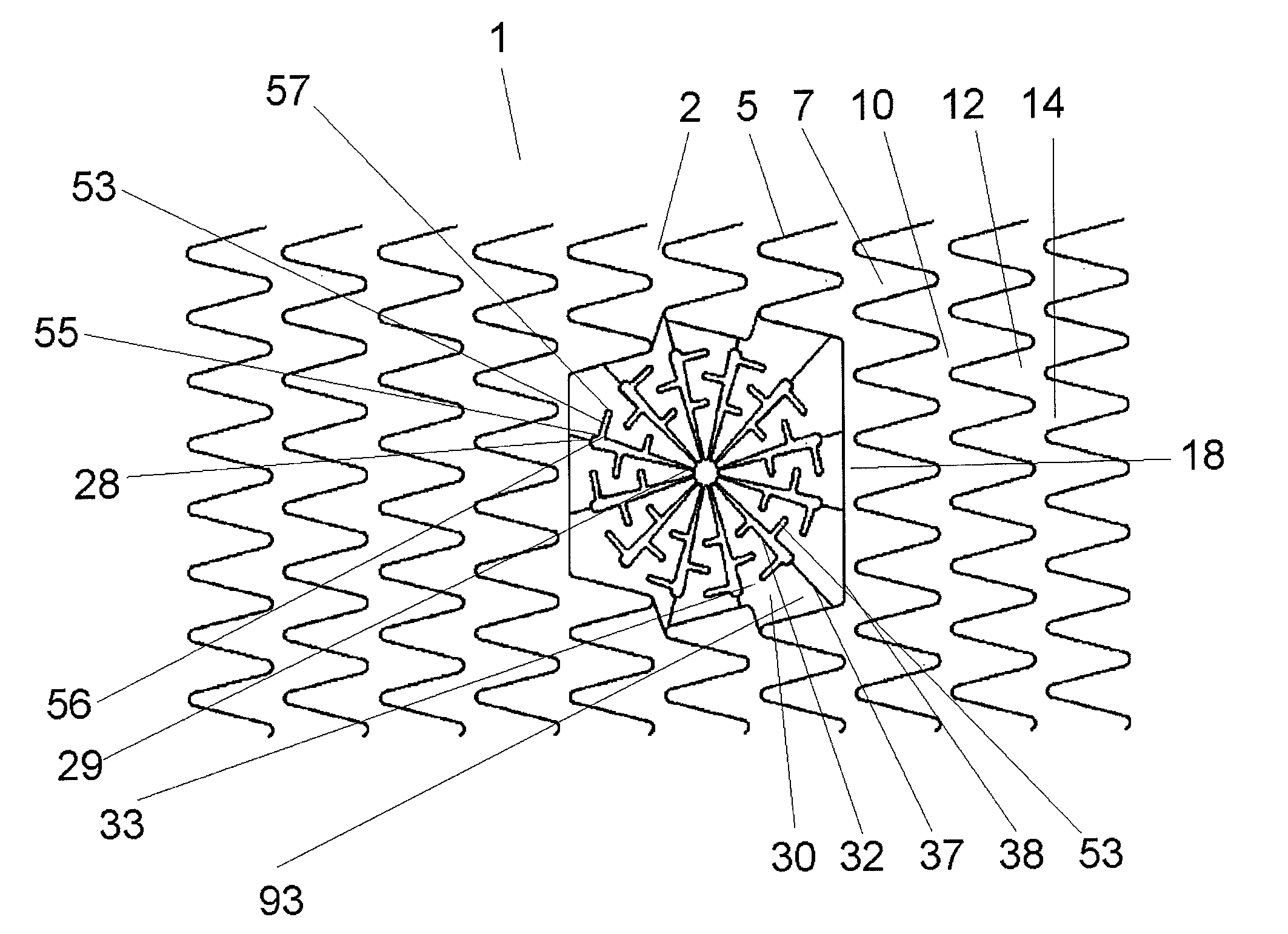
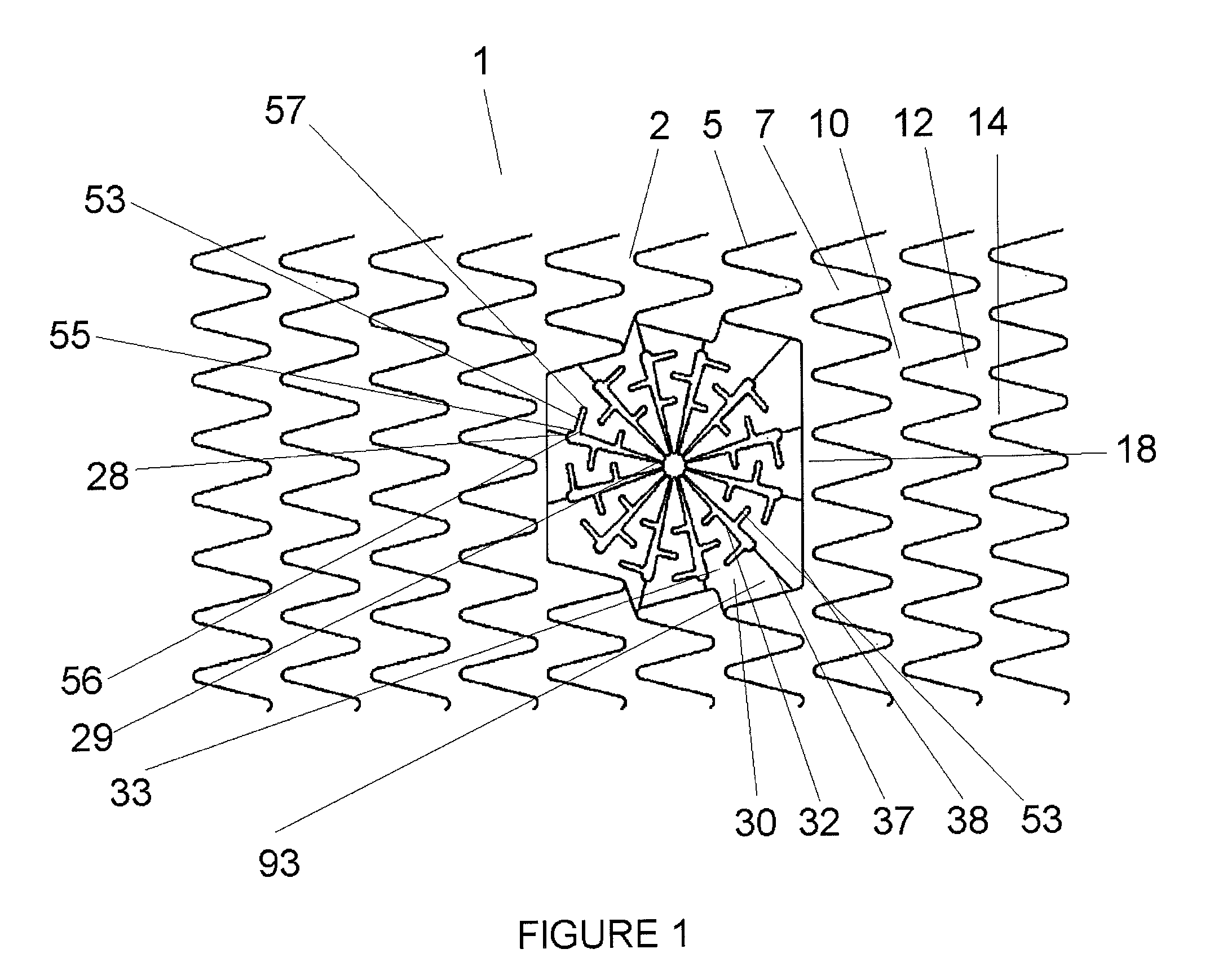
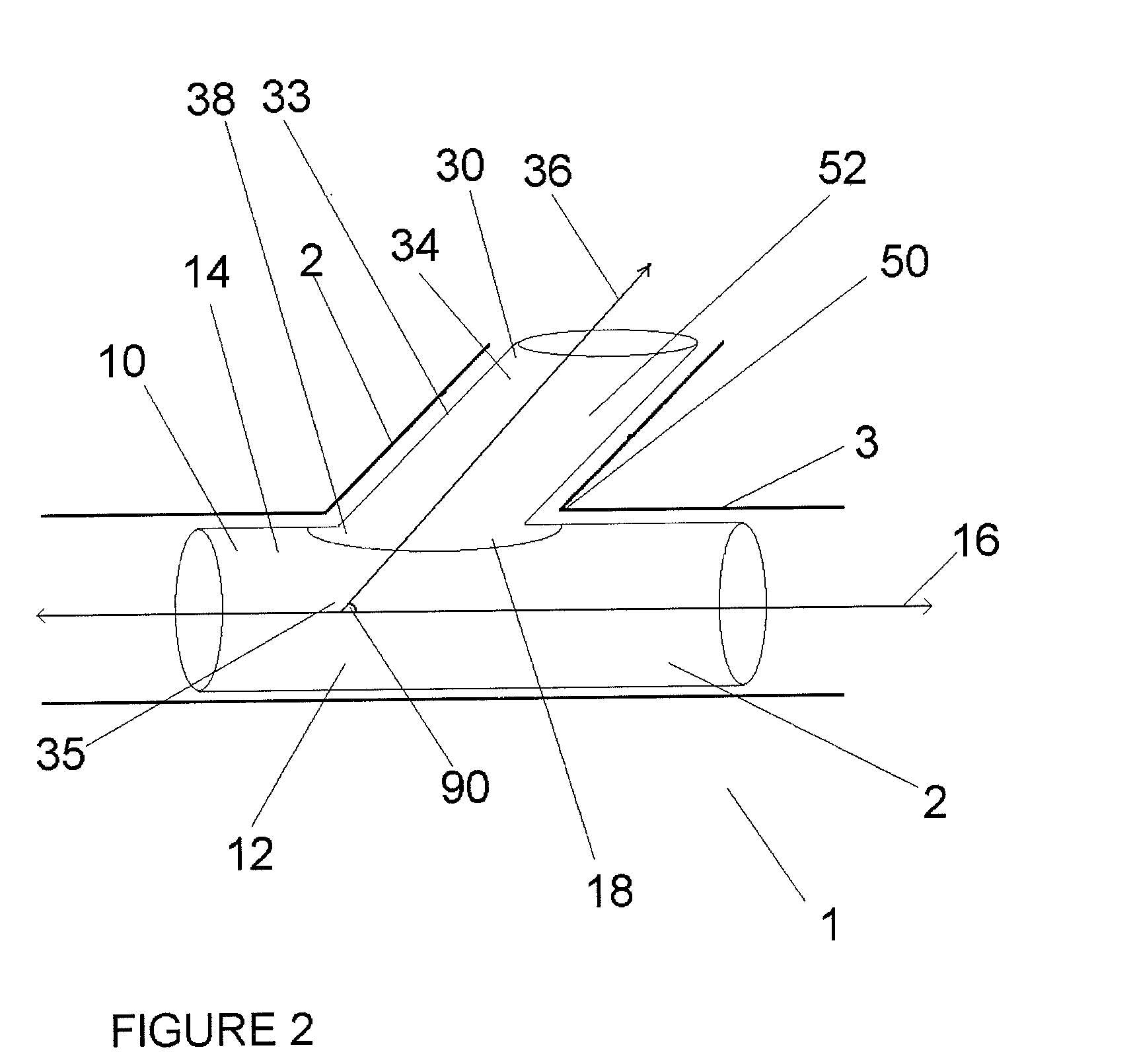
[0070]Referring now to FIG. 1 there is shown an embodiment featuring an unexpanded substantially tubular bifurcated stent 1 which comprises a first stent body 10, a side branch opening 30 along its surface, and a side branch assembly 30 adjacent to and covering at least a portion of the side branch opening 30. Although in some embodiments the side branch opening...


PUM


Abstract

A bifurcated stent that uses turning segments to reduce the strain at regions which bend at extreme angles. The turning segments can be placed on side branch petals or on connectors connecting the petals to the stent body. Combining the turning segments with connectors of different length and tethers provides for a stent with high flexibility that can accommodate various shaped body vessels. This design allows the bifurcation branch to extend easily, to a useful distance, and to be deployed along oblique angles. Best of all, this design avoids the problems of angularly strained side branch.

Description

CROSS-REFERENCE TO RELATED APPLICATIONS[0001]This application claims priority to U.S. Application No. 60 / 815,950, filed Jun. 23, 2006, the entire contents of which is incorporated herein by reference.STATEMENT REGARDING FEDERALLY SPONSORED RESEARCH[0002]Not ApplicableBACKGROUND OF THE INVENTIONField of the Invention[0003]In some embodiments this invention relates to implantable medical devices, their manufacture, and methods of use. Some embodiments are directed to delivery systems, such as catheter systems of all types, which are utilized in the delivery of such devices.[0004]A stent is a medical device introduced to a body lumen and is well known in the art. Typically, a stent is implanted in a blood vessel at the site of a stenosis or aneurysm endoluminally, i.e. by so-called “minimally invasive techniques” in which the stent in a radially reduced configuration, optionally restrained in a radially compressed configuration by a sheath and / or catheter, is delivered by a stent deliv...

Claims


Application Information

Patent Timeline
IPC IPC(8): A61F2/06
CPCA61F2/856A61F2/91A61F2/915A61F2002/91508A61F2230/005A61F2002/91525A61F2002/91533A61F2002/91575A61F2002/91516
Inventor GREGORICH, DANIELGROTHEIM, KEVINMEYER, MICHAEL P.SORENSON, SHAWNROBAINA, SAMUEL
Owner BOSTON SCI SCIMED INC
Why Eureka
Try Eureka