
Audio Encoding Apparatus, Audio Decoding Apparatus, Communication Apparatus and Audio Encoding Method

a technology of audio encoding and audio decoding, which is applied in the field of speech encoding apparatus speech encoding apparatus, communication apparatus and speech encoding methods, can solve the problem that the encoding scheme is not very robust against frame loss, and achieves the effect of avoiding error propagation, improving error robustness, and reliably improving the quality of speech

Inactive Publication Date: 2007-12-27
III HLDG 12 LLC
View PDF16 Cites 72 Cited by
  • Summary
  • Abstract
  • Description
  • Claims
  • Application Information

AI Technical Summary

Benefits of technology

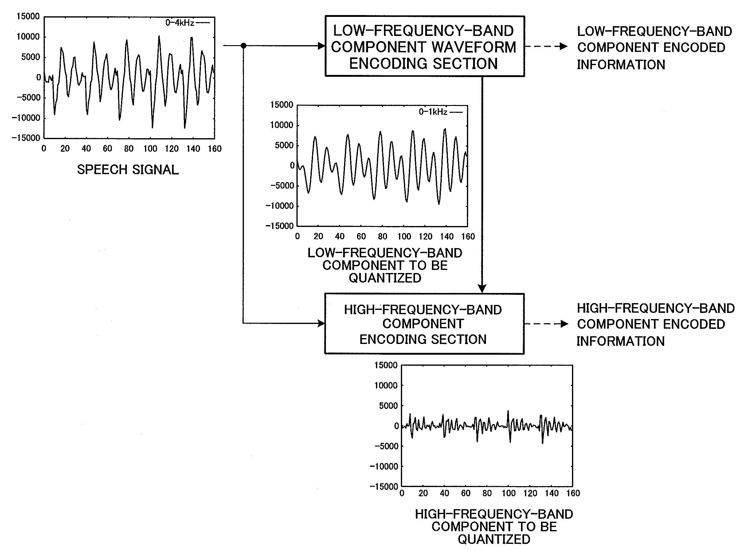
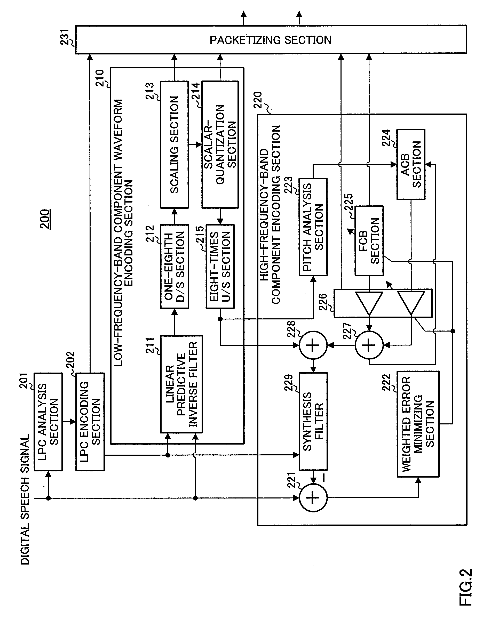
[0011] According to the present invention, a low-frequency-band component (for example, a low-frequency component less than 500 Hz) of a speech signal which is significant in auditory perception is encoded with the encoding scheme independent from a memory—a scheme without using inter-frame prediction—, for example, a waveform encoding scheme or an encoding scheme in the frequency domain, and a high-frequency-band component in the speech signal is encoded with the CELP scheme using the adaptive codebook and fixed codebook. Therefore, in the low-frequency-band component of the speech signal, error propagation is avoided, and it is made possible to perform concealing processing through interpolation using correct frames prior and subsequent to a lost frame. Therefore, the error robustness is improved in the low-frequency-band component. As a result, according to the present invention, it is possible to reliably improve the quality of speech reproduced by a communication apparatus provided with the speech decoding apparatus.
[0012] Further, according to the present invention, since the encoding scheme such as waveform encoding and the like without using inter-frame prediction is applied to the low-frequency-band component of the speech signal, it is possible to suppress a data amount of speech data generated through encoding of the speech signal to a required minimum amount.
[0013] Furthermore, according to the present invention, frequency band of the low-frequency-band component of the speech signal is always set so as to include a fundamental frequency (pitch) of speech, so that it is possible to calculate pitch lag information of the adaptive codebook in the high-frequency-band component encoding section using a low-frequency-band component of the excitation signal decoded from the low-frequency-band component encoded information. By this feature, according to the present invention, even when the high-frequency-band component encoding section neither encodes nor transmits the pitch lag information as the high-frequency-band component encoded information, the high-frequency-band component encoding section is capable of encoding the high-frequency-band component of the speech signal using the adaptive codebook. Moreover, according to the present invention, when the high-frequency-band component encoding section encodes the pitch lag information as the high-frequency-band component encoded information to transmit, the high-frequency-band component encoding section is capable of efficiently quantizing the pitch lag information with a small number of bits by utilyzing the pitch lag information calculated from a decoded signal of the low-frequency-band component encoded information.

Problems solved by technology

Therefore, the CELP scheme is not regarded as being very robust against frame loss.

Method used


Image

  • Audio Encoding Apparatus, Audio Decoding Apparatus, Communication Apparatus and Audio Encoding Method
  • Audio Encoding Apparatus, Audio Decoding Apparatus, Communication Apparatus and Audio Encoding Method
  • Audio Encoding Apparatus, Audio Decoding Apparatus, Communication Apparatus and Audio Encoding Method

Examples


Embodiment Construction

[0020] One embodiment of the present invention will be described in detail below with reference to the accompanying drawings as appropriate.

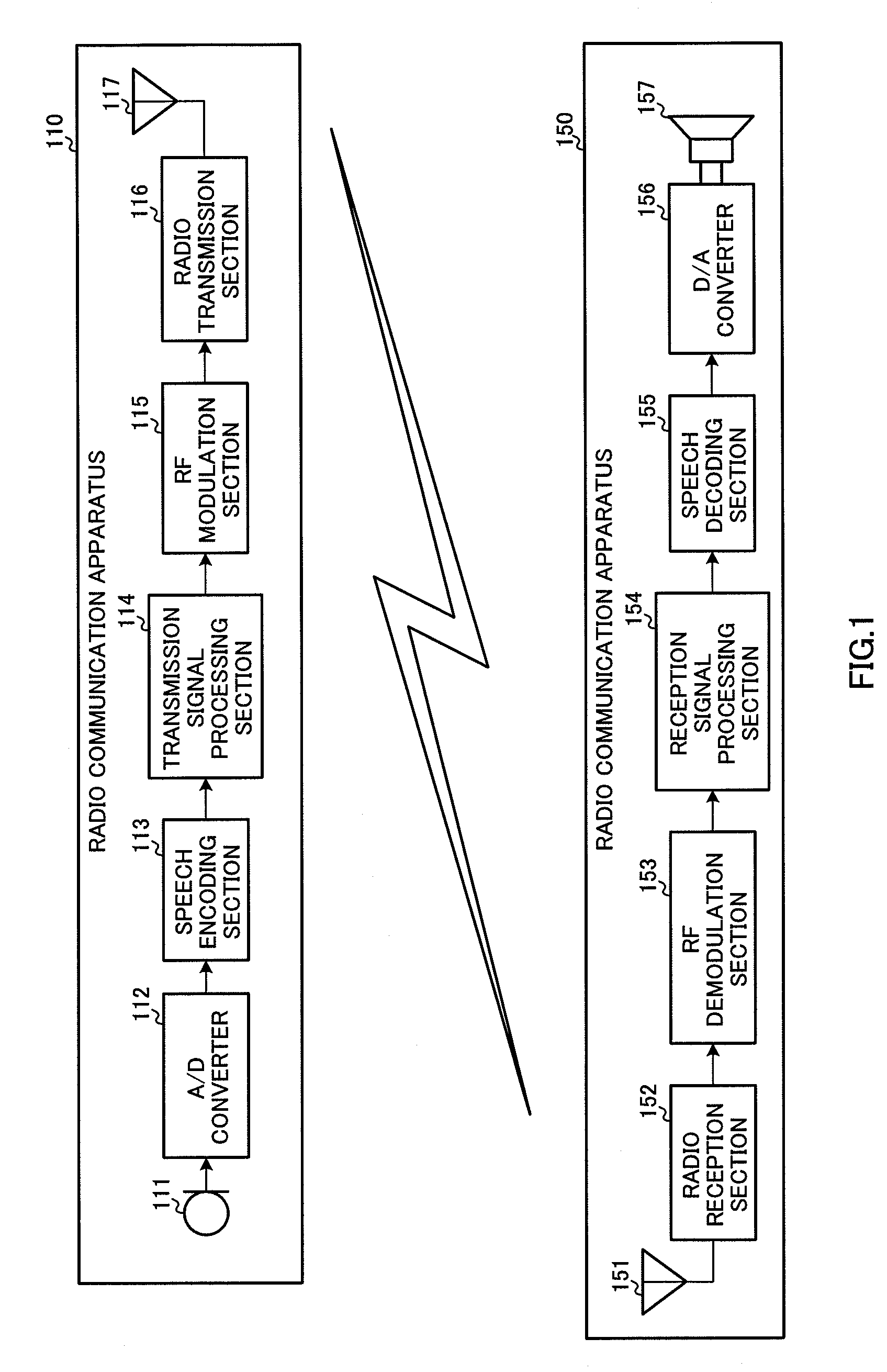
[0021]FIG. 1 is a block diagram showing a configuration of a speech signal transmission system including radio communication apparatus 110 provided with a speech encoding apparatus according to one embodiment of the present invention, and radio communication apparatus 150 provided with a speech decoding apparatus according to this embodiment. In addition, radio communication apparatuses 110 and 150 are radio communication apparatuses in a mobile communication system of mobile telephone and the like, and mutually transmit and receive radio signals via a base station apparatus not shown in the figure.

[0022] Radio communication apparatus 110 has speech input section 111, analog / digital (A / D) converter 112, speech encoding section 113, transmission signal processing section 114, radio frequency (RF) modulation section 115, radio transmission secti...


PUM


Abstract

An audio encoding apparatus capable of improving the frame cancellation error tolerance, without increasing the number of bits of a fixed code book, in a CELP type audio encoding. In this apparatus, a low frequency component waveform encoding part (210) calculates, based on a quantized LPC received from an LPC encoding part (202), a linear prediction residual signal of a digital audio signal received from an A / D converter (112), then performs a down sampling of the calculation result to extract the low frequency components comprising bands, which are lower than a predetermined frequency, in the audio signal, and then waveform encodes the extracted low frequency components to produce encoded low-frequency component information. Then, the low frequency component waveform encoding part (210) inputs this encoded low-frequency component information to a packetizing part (231), while inputting the quantized low-frequency component waveform encoded signal (sound source waveform), which has been produced by the waveform encoding, to a high frequency component encoding part (220).

Description

TECHNICAL FIELD [0001] The present invention relates to a speech encoding apparatus, speech decoding apparatus, communication apparatus and speech encoding method using a scalable encoding technique. BACKGROUND ART [0002] Conventionally, in a mobile radio communication system and the like, a CELP (Code Excited Linear Prediction) scheme has been widely used as an encoding scheme for speech communication, since speech signals can be encoded with high quality at relatively low bit rates (about 8 kbit / s in telephone band speech). Meanwhile, in recent years, speech communication (VoIP: Voice over IP) using an IP (Internet Protocol) network is rapidly becoming widespread, and it is foreseen that the technique of VoIP will be used widely in the mobile radio communication system. [0003] In packet communication typified by IP communication, since packets are sometimes lost on the transmission path, a scheme that is robust against frame loss is preferable as a speech encoding scheme. Herein, ...

Claims


Application Information

Patent Timeline
IPC IPC(8): G10L13/00G10L19/02G10L19/005G10L19/08G10L19/125G10L19/16G10L19/24G10L25/18
CPCG10L19/005G10L25/18G10L19/24
Inventor EHARA, HIROYUKI
Owner III HLDG 12 LLC
Learn More