Compressor crankshaft, particularly refrigerant compressor crankshaft, and method for grinding such a crankshaft

a compressor and crankshaft technology, applied in the direction of machines/engines, manufacturing tools, positive displacement liquid engines, etc., can solve the problem of extending the life of grinding tools, and achieve the effect of guiding the shaft element so accurately, reducing the diameter, and improving the accuracy of grinding the shaft section

Inactive Publication Date: 2008-01-03
SECOP GMBH +1
View PDF11 Cites 1 Cited by
  • Summary
  • Abstract
  • Description
  • Claims
  • Application Information

AI Technical Summary

Benefits of technology

[0010]If it is desired to grind such a crankshaft on its shaft element, the crankshaft blank can be inserted in the working machine and positioned very accurately by means of the transition element. The transition element has at least two reference points, so that a positioning is possible in two directions. With a positioning in two directions, the transition element can, however, be positioned so that the shaft axis, for example the axis of the shaft element, corresponds to the rotation axis of the grinding machine. When, now, the position of the shaft element has been fixed in this way, the grinding disc can relatively quickly be engaged on the shaft section. A grinding disc can be chosen to determine the contour of the shaft section. When, during grinding, the crankshaft is held on the transition element, a centre-less grinding no longer has to be used, which improves the accuracy of the working.
[0025]Preferably, a clamping element is used for the axial positioning, said element acting upon the end of the shaft element facing away from the transition element in a section of the shaft element with reduced diameter. The clamping element can act upon a conical section of the shaft element, so that the clamping element can be used during grinding, not only to hold the shaft element in the axial direction, but also to centre the shaft element. This further improves the accuracy during grinding of the shaft section without increasing the costs significantly.

Problems solved by technology

Further, no lateral forces occur on the grinding tool, so that the grinding tool has a longer life.

Method used


Image

  • Compressor crankshaft, particularly refrigerant compressor crankshaft, and method for grinding such a crankshaft
  • Compressor crankshaft, particularly refrigerant compressor crankshaft, and method for grinding such a crankshaft
  • Compressor crankshaft, particularly refrigerant compressor crankshaft, and method for grinding such a crankshaft

Examples


Embodiment Construction

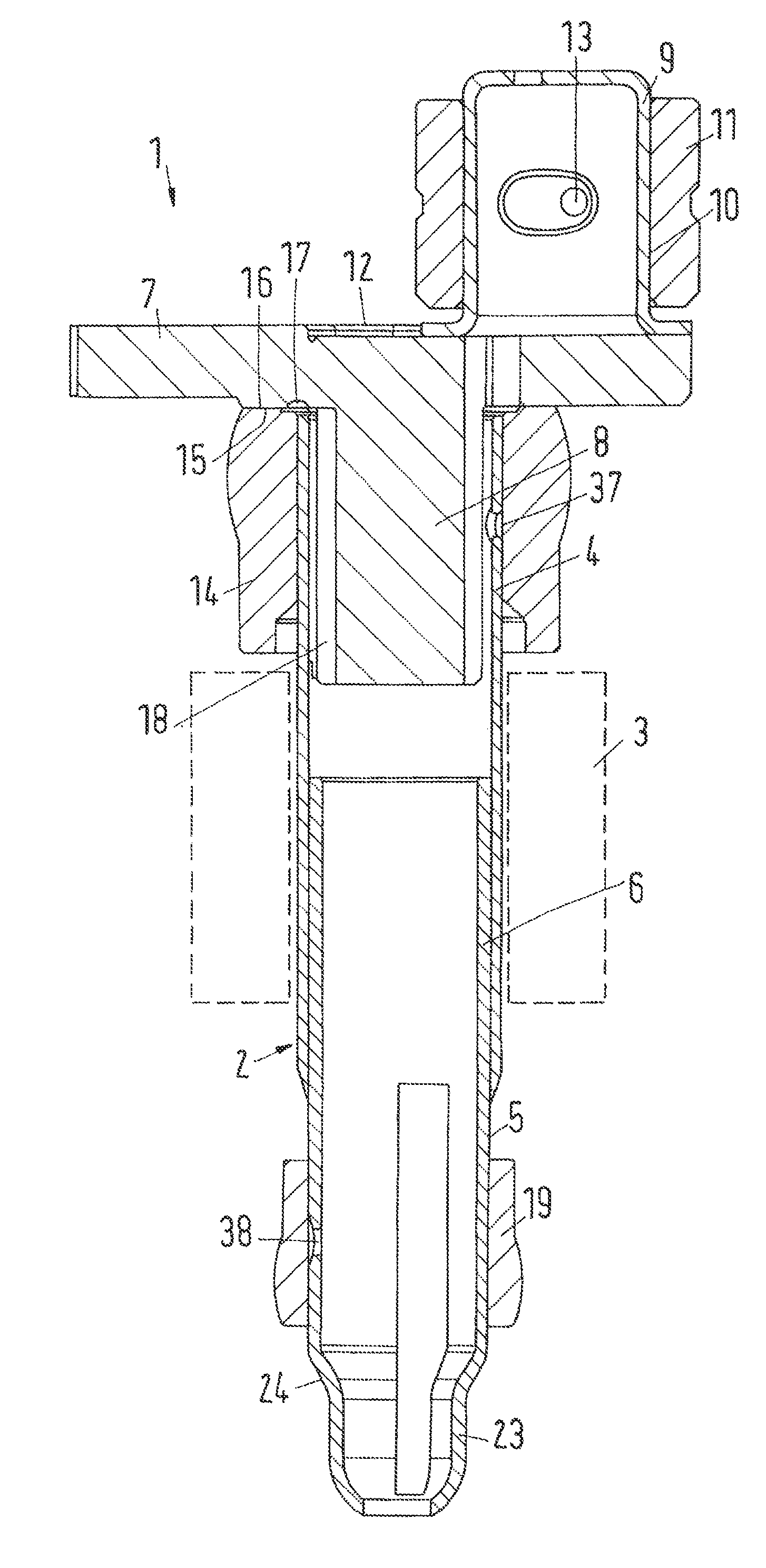
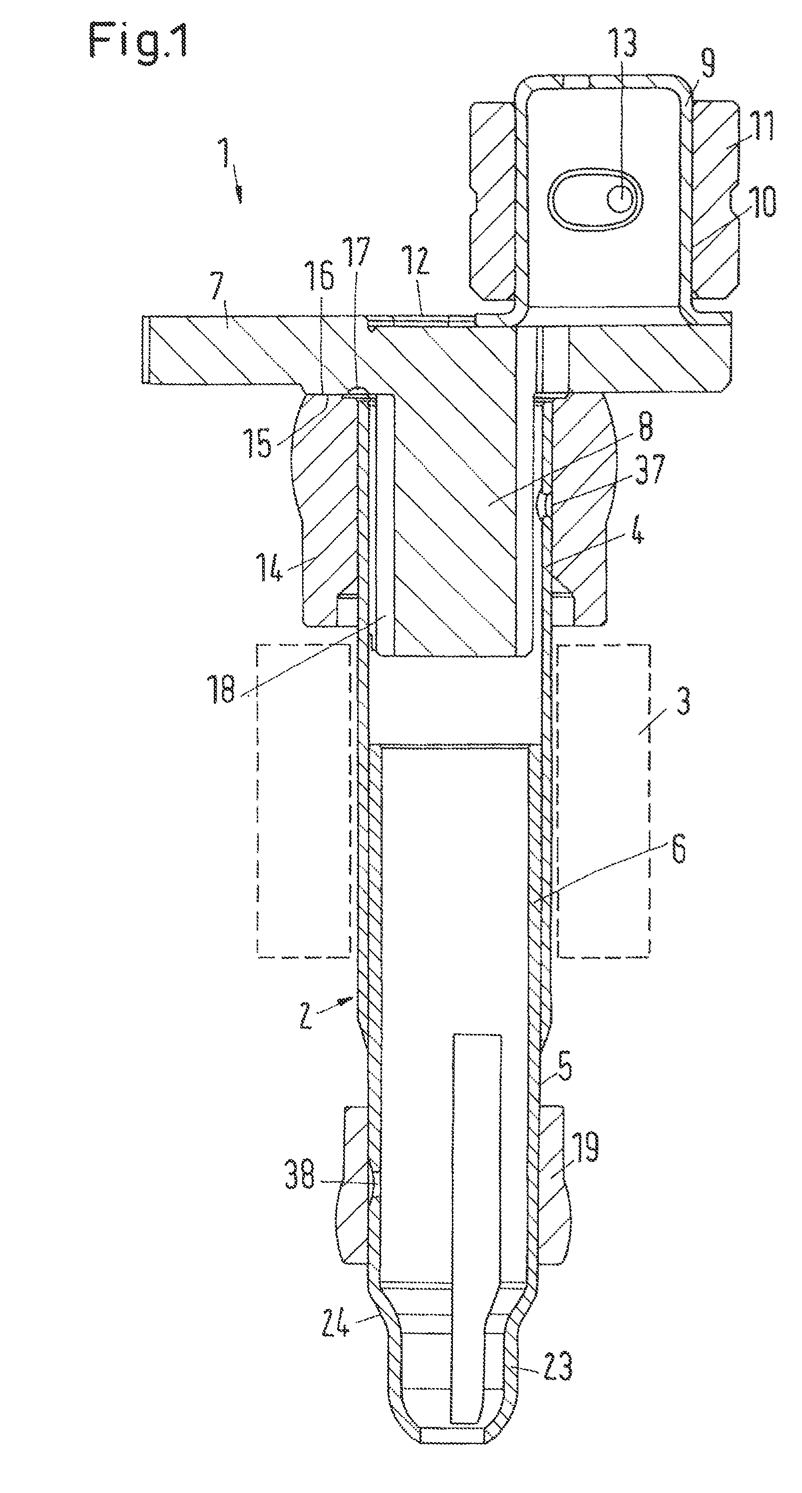
[0032]A crankshaft 1 of a refrigerant compressor shown in FIG. 1 has a shaft element 2, which is designed to be connected to a merely schematically shown rotor 3 of an electrical drive motor. The shaft element 2 is made of two telescopically joined sections 4, 5, which are connected to each other, for example by welding, in an overlapping section 6.

[0033]Such a crankshaft 1 is usually driven in the shown position, in which the shaft element is substantially vertically oriented. For reasons of simplicity directions will in the following be called “up” or “down” and the like, said terms referring to the views in FIGS. 1, 2 and 4. However, no definite spatial fixing of the crankshaft 1 is given.

[0034]A transition element 7 is located at the upper end of the section 4 of the shaft element 2. The transition element 7 is made as a sintered or extrusion moulded part, particularly a cold formed part. It can therefore be made with a high accuracy, without requiring further working steps for ...


PUM


Abstract

The invention concerns a compressor crankshaft, particularly a refrigerant compressor crankshaft (1) and a method for manufacturing such a crankshaft, with a shaft element (2), a crank pin (9) located eccentrically to the shaft element and a transition element (7) between the shaft element (2) and the crank pin (9). The purpose of the invention is to keep the manufacturing costs low. For this purpose, it is ensured that along its circumference the transition element (7) has at least one first reference point (20) and one second reference point (21a, 21b), with which the transition element (7) can be positioned in a holding fixture (25) of a working machine.

Description

CROSS REFERENCE TO RELATED APPLICATIONS[0001]Applicant hereby claims foreign priority benefits under U.S.C. § 119 from German Patent Application No. 10 2006 030 492.6 filed on Jul. 1, 2006, the contents of which are incorporated by reference herein.FIELD OF THE INVENTION[0002]The invention concerns a compressor crankshaft, particularly a refrigerant compressor crankshaft, with a shaft element, a crank pin located eccentrically to the shaft element and a transition element between the shaft element and the crank pin. Further, the invention concerns a method for grinding a compressor crankshaft, particularly a refrigerant compressor crankshaft, with a shaft element, a crank pin and a transition element between the shaft element and the crank pin, the circumference of the shaft element being ground.BACKGROUND OF THE INVENTION[0003]In the following the invention is described on the basis of a crankshaft meant for a refrigerant compressor.[0004]Refrigerant compressors in the form of plun...

Claims


Application Information

Patent Timeline
Patent Type & Authority Applications(United States)
IPC IPC(8): F16C3/04B24B7/00
CPCB24B5/421Y10T74/2173F16C3/04F04B39/0094
Inventor IVERSEN, FRANK HOLMLASSEN, HEINZ OTTONOMMENSEN, MARTENHANDKE, EKKEHARD
Owner SECOP GMBH
Why Eureka
Try Eureka