Control device of vehicle

Pending Publication Date: 2022-09-08
TOYOTA JIDOSHA KK
View PDF0 Cites 0 Cited by
  • Summary
  • Abstract
  • Description
  • Claims
  • Application Information

AI Technical Summary

Problems solved by technology

However, there is a possibility that, when a torque is input to a mechanical transmission device, an engagement shock occurs when the command pressure of the predetermined engagement device is increased stepwise or the predetermined engagement device cannot be quickly engaged even when the command

Method used


Image

  • Control device of vehicle
  • Control device of vehicle
  • Control device of vehicle

Examples


Embodiment Construction

[0028]In the following, an embodiment of the present disclosure will be described in detail with reference to the drawings.

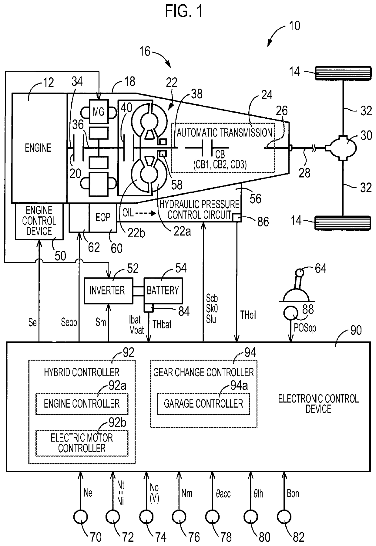
[0029]FIG. 1 is a diagram for describing a schematic configuration of a vehicle 10 to which the present disclosure is applied, and is a diagram for describing a control function and a main part of a control system for various controls in the vehicle 10. In FIG. 1, the vehicle 10 is a hybrid vehicle including an engine 12 and an electric motor MG that are drive force sources for traveling. Moreover, the vehicle 10 includes drive wheels 14 and a power transmission device 16 provided in a power transmission path between the engine 12 and the drive wheels 14.

[0030]The engine 12 is a known internal combustion engine, such as a gasoline engine or a diesel engine. In the engine 12, an engine torque Te that is an output torque of the engine 12 is controlled by controlling an engine control device 50 including a throttle actuator, a fuel injection device, an ignition dev...


PUM


Abstract

In a case where a predetermined switching operation to a state in which a traveling position is selected from a state in which another shift position of a mechanical transmission device is selected is performed by a driver, a quick engagement command to quickly engage a predetermined engagement device is performed in a state in which output of a predetermined torque is stopped, and then a rapid garage control of increasing a rotation speed of an electric motor at a rotation speed equal to or higher than a predetermined rotation speed is executed. The rapid garage control is executed in a case where a predetermined start condition is established.

Description

CROSS-REFERENCE TO RELATED APPLICATION[0001]This application claims priority to Japanese Patent Application No. 2021-034841 filed on Mar. 4, 2021, incorporated herein by reference in its entirety.BACKGROUND1. Technical Field[0002]The present disclosure relates to a control device of a vehicle including a mechanical transmission device that transmits drive force from a drive force source including an electric motor.2. Description of Related Art[0003]A control device of a vehicle including an electric motor, and a mechanical transmission device that includes a predetermined engagement device, in which a traveling position at which the mechanical transmission device can transmit drive force from the electric motor is formed as a shift position by putting the predetermined engagement device into an engaged state. For example, there is a drive device of a hybrid vehicle disclosed in Japanese Unexamined Patent Application Publication No. 2015-217914 (JP 2015-217914 A). JP 2015-217914 A di...

Claims


Application Information

Patent Timeline
IPC IPC(8): B60W20/30B60W20/20B60W40/09
CPCB60W20/30B60W20/20B60W40/09B60W2510/10B60W2510/081B60W10/08B60W10/06B60W10/11B60W30/20Y02T10/72B60K6/48B60K2006/4825B60W10/10B60W2710/081B60W2710/083B60W30/18063B60W2540/16B60W2510/1015B60W2510/104B60W2540/10B60W10/02B60W2710/021B60W2510/107B60K6/387B60K6/547B60W10/0235B60W10/023B60W2710/023B60W20/15B60W30/18036F16H2061/0488F16H61/20F16H2061/207
Inventor HASEGAWA, YOSHIOCHIMBE, TOMOHIROKAWAI, SHOGO
Owner TOYOTA JIDOSHA KK
Why Eureka
Try Eureka