Cotton conditioning device

a conditioning device and cotton technology, applied in the field of cotton conditioning devices, can solve the problems of brittleness of cotton fibers with too low moisture content, affecting the quality of cotton, falling out of favor of poor people, etc., and achieve the effect of effective and efficient addition of moisture to lint cotton

Active Publication Date: 2008-01-10
CHEROKEE FABTION
View PDF8 Cites 8 Cited by
  • Summary
  • Abstract
  • Description
  • Claims
  • Application Information

AI Technical Summary

Benefits of technology

[0013]Another object of the present invention is to provide a device which effectively and efficiently adds moisture to lint cotton during the baling process.
[0014]Another object of the present invention is to provide a cotton conditioning device which can be manufactured and sold at a reasonable price and added to existing cotton processing lines.

Problems solved by technology

For example, cotton fibers with too low of a moisture content become brittle and are prone to breakage.
One common method, falling out of favor for its poor results, is simply to set up an atomized mister above the slide that moves the cotton batt to the baler, spraying water directly onto the surface of the cotton.
The thicker the batt, the less desirable this method becomes.
When moisture is added in this way, it is very easy to add too much water to a bale, thus making it prone to damage from rotting.
This method can also be deceitful since excess water weight can easily be added to a bale (cotton being sold by weight).
When a spray system is used on a thick batt, the layering effect described above can potentially create micro layers of moisture-damaged cotton and good cotton throughout a bale, thus rendering the entire bale useless.
Although this system is effective, it is inefficient because the rate of moisturization of the device cannot keep up with current capacity requirements.
The capacity of a slide grid humidifier can be increased by adding length to the slide, but it is impractical to elongate slides further due to factory building height limitations.
Furthermore, current batts are thicker than batts produced in the past and it is difficult to pass humid air through them uniformly by applying only a positive pressure on one side, resulting in an uneven distribution of moisture throughout the batt.

Method used


Image

  • Cotton conditioning device
  • Cotton conditioning device
  • Cotton conditioning device

Examples


Embodiment Construction

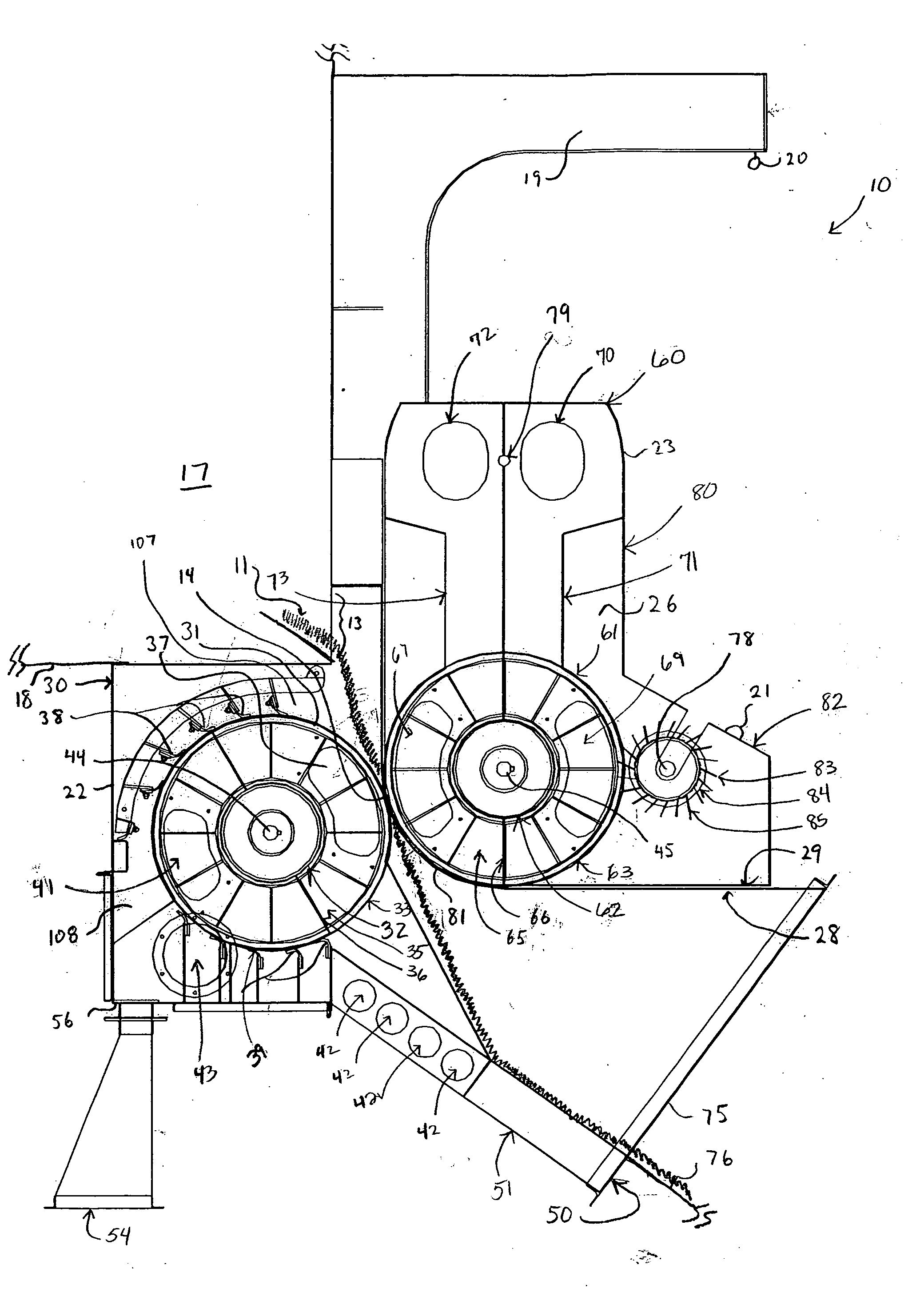
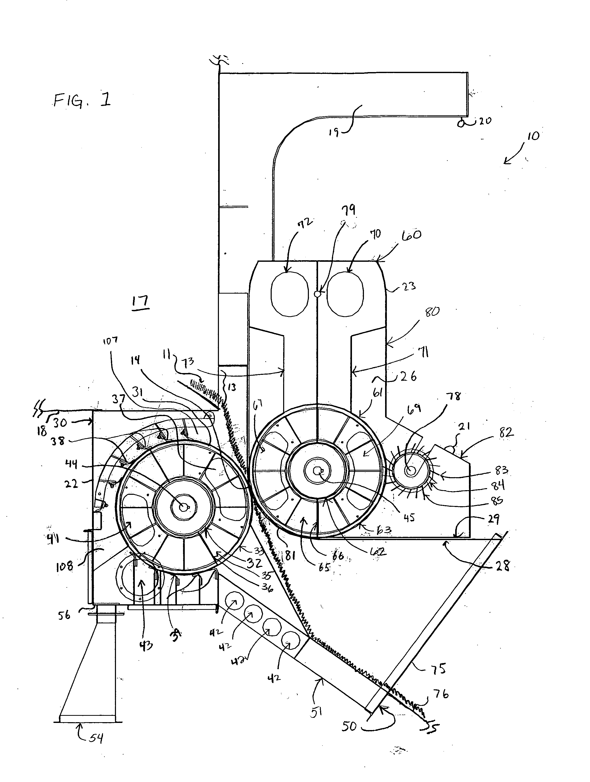
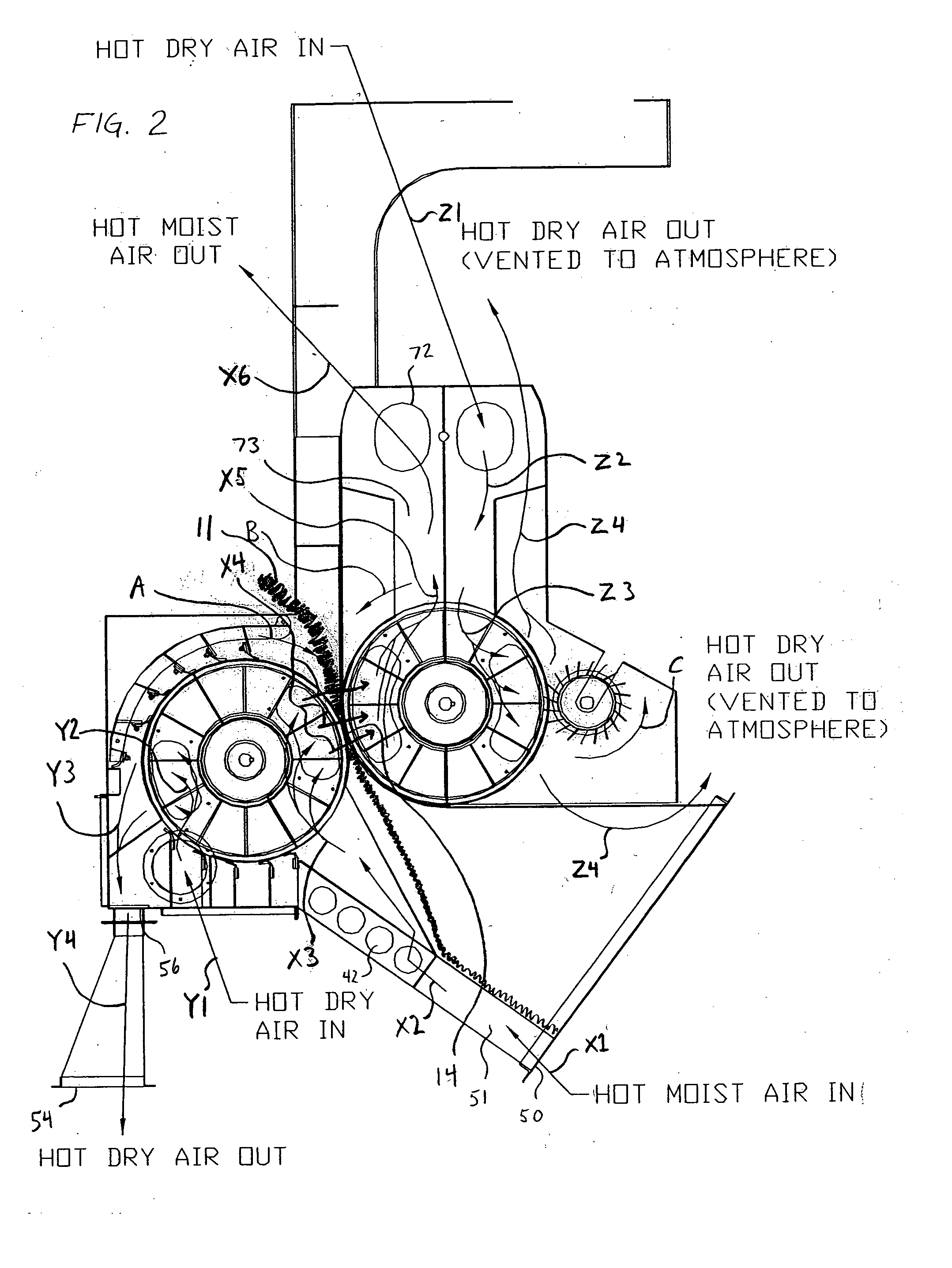
[0021]As illustrated in a schematic side view in FIG. 1, this invention teaches a cotton conditioning device 10 for adding moisture to cotton lint prior to the baling process. The cotton conditioning device 10 of the present invention consists of a stationary unit 30 and a suspended unit 60 positioned in mating contact with the stationary unit 30 along mating surfaces 28 and 29, respectively.

[0022]As best shown in FIG. 3, the stationary unit 30 comprises a housing 22 containing a cylindrical, rotatable lower drum 31 on an axial shaft 44 running through a first side 24 of the housing 22 and a first opposing end of the drum 31, to a second opposing end of the drum 31 and an opposing second side 25 of the housing 22. The opposing ends of the drum 31 are substantially covered or capped by the solid, non-permeable first and second sides 24, 25 of the housing 22 which remain stationary as the drum 31 rotates. Each first and second side 24, 25 of the housing 22 further comprise a mating su...


PUM

PropertyMeasurementUnit
thickaaaaaaaaaa
curvatureaaaaaaaaaa
movementaaaaaaaaaa

Abstract

The present invention related generally to a device for adding moisture to fibrous material such as cotton. The conditioning device receives a continuous cotton batt from a battery condenser. The continuous cotton batt is fed between two opposing drums. Hot moist air is fed into one drum and drawn out of the perforated surface of the drum, through the batt as it is being compressed between the two drums, and into the other drum. The opposing drums are internally compartmented by a plurality of longitudinal staves, each compartment being covered by a corresponding segment of the perforated surface. Hot dry air is fed into the compartments of the drums when the corresponding segment of the surface is not carrying the cotton batt in order to dry the surface of the drum and clear the perforations of any lint that might have been retained on the surface.

Description

FIELD OF THE INVENTION[0001]This invention relates in general to processing fibrous materials, and in particular to a device for humidifying lint cotton and other fibrous materials and compressing the material to increase its density.[0002]The present invention relates generally to a cotton conditioning device for adding moisture to lint cotton prior to the baling process. The device can be used with any existing cotton gin battery condenser. The device can be used as an attachment to receive a cotton batt from any existing battery condenser by attaching it intermediate the battery condenser and a slide configured to receive the humidified and compressed batt from the conditioning device. The device humidifies lint cotton by receiving a batt of lint cotton and compressing it at a nip point between two opposing, counter-rotating drums housed side-by-side with one drum being slightly elevated relative to the other. As the cotton lint is compressed between the two opposing drums, moist...

Claims


Application Information

Patent Timeline
Patent Type & Authority Applications(United States)
IPC IPC(8): D01G37/00D01G99/00
CPCD01G23/00D01G99/005D01G25/00
Inventor CORY, MARK D.
Owner CHEROKEE FABTION
Why Eureka
Try Eureka