
Bicycle Suspension System

a suspension system and bicycle technology, applied in the direction of shock absorbers, cycle springs, steering devices, etc., can solve the problems of forks that cannot tube length may need to be increased to accommodate the suspension system, and the fork may not be able to handle some fore/aft loading, etc., to achieve the effect of facilitating axial sliding motion

Inactive Publication Date: 2008-01-10
SRAM CORPORATION
View PDF13 Cites 10 Cited by
  • Summary
  • Abstract
  • Description
  • Claims
  • Application Information

AI Technical Summary

Benefits of technology

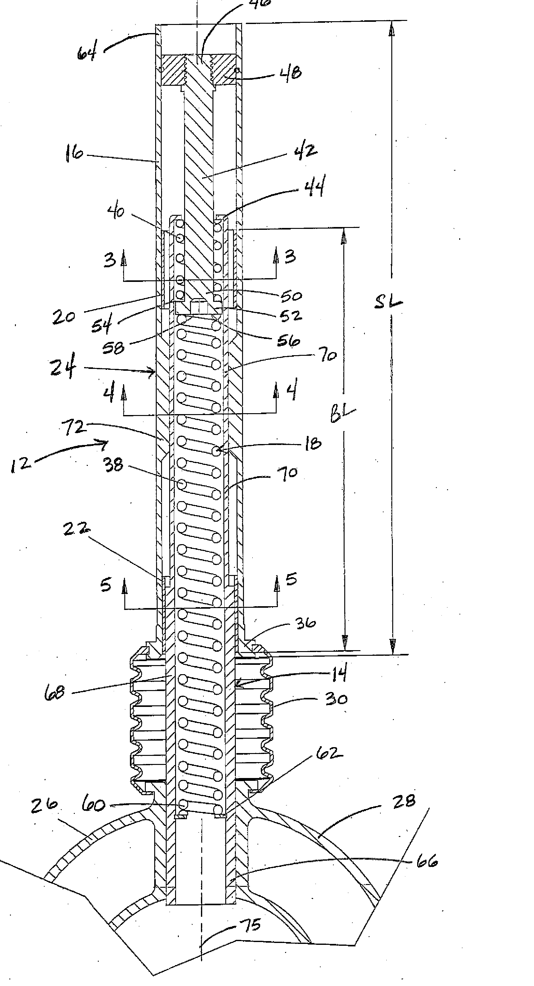
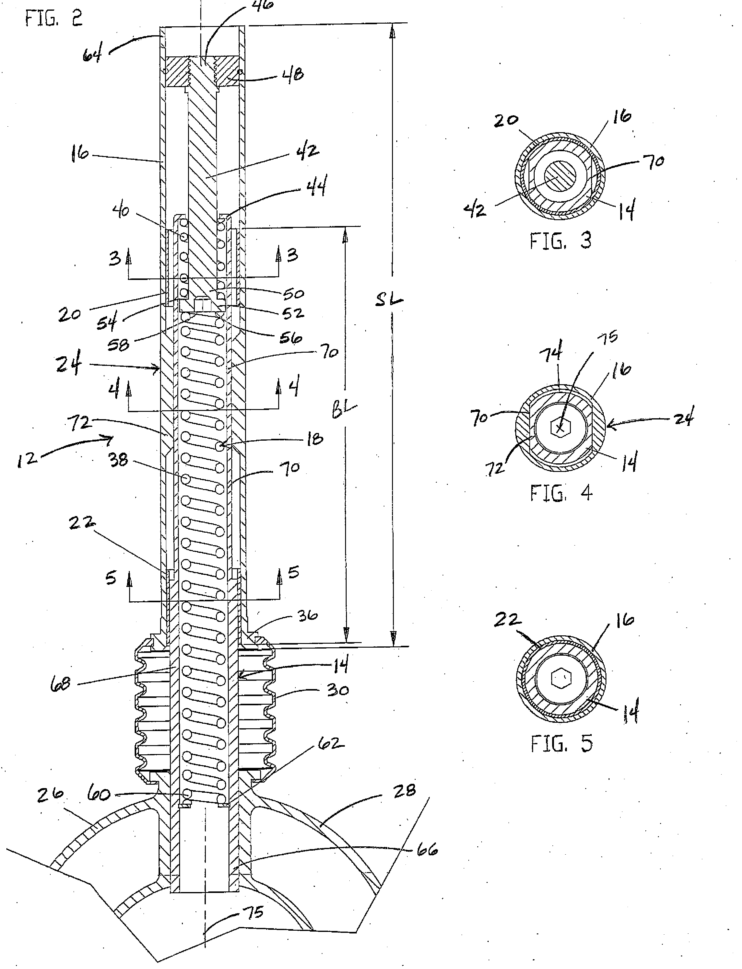
[0003]The present invention provides a bicycle suspension system. The suspension system generally includes inner and outer tubes, first and second bushings, a steering control mechanism and a shock-absorbing mechanism. The first and second bushings are disposed between the inner and outer tubes to facilitate axial sliding motion of the inner tube within the outer tube in response to suspension loading. The first and second bushings do not transmit any appreciable torque between the inner and outer tubes. The steering control mechanism prevents relative rotation between the inner and outer tubes. The shock-absorbing mechanism absorbs the loads applied to the suspension system.
[0004]In one embodiment of the present invention, the steering control mechanism is disposed between the first and second bushings. The steering control mechanism includes a noncircular outer surface of the inner tube mating with a complimentary-shaped noncircular inner surface of the outer tube. Preferably, a portion of the inner tube has a double-D shaped outer surface mating with a complimentary-shaped inner surface of the outer tube. More preferably, the outer surface of the inner tube may include two flat sections and two curved sections. A clearance between the inner and outer tubes at the curved sections may be provided to permit relative motion between the inner and outer tubes transverse to an outer tube axis. So configured, the distance between the first and second bushings along the length of the tubes may be large relative to the diameter of the inner tube. The distance between the first and second bushings is referred to as bushing length and is measured from the top of the first or upper bushing to the bottom of the second or lower bushing. In the present invention, the ratio of the bushing length to the inner tube diameter is greater than 4 or preferably approximately 5.8. This allows the fork to handle fore / aft or lateral loading without binding. Further, this configuration minimizes the length of the steerer tube.
[0006]Further, this spring arrangement minimizes the crown-to-axle length Typically, suspension forks have a crown-to-axle length that is greater than those of rigid forks. Ideally, the crown-to-axle length of a suspension fork should only be increased by the amount of suspension travel. Typically, a suspension fork adds 50 mm to the crown-to-axle length while only providing 25 mm of travel. The present invention provides 40 mm of travel while only increasing the crown-to-axle dimension by 40 mm.

Problems solved by technology

One drawback of this type of suspension is that the fork may not be able to handle some fore / aft loading when the distance between the two bushings, or the bushing length, is too small.
This may lead to binding of the fork.
Another drawback of suspension systems in the head or steerer tubes is that the tube length may need to be increased to accommodate the suspension system.

Method used


Image

  • Bicycle Suspension System
  • Bicycle Suspension System
  • Bicycle Suspension System

Examples


Embodiment Construction

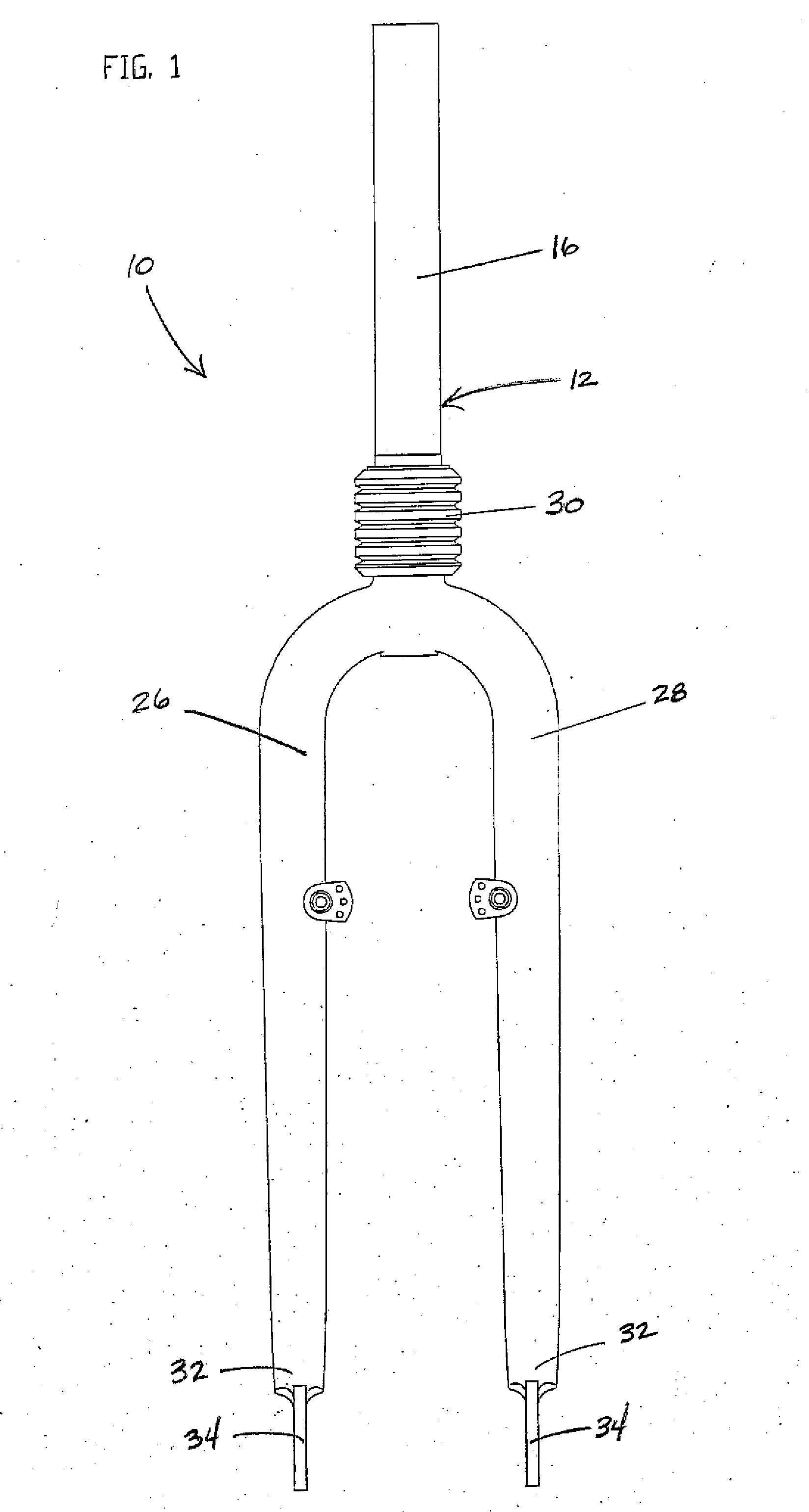
[0015]FIGS. 1-5 illustrate a bicycle front fork 10 with a suspension system 12 associated with a head tube (not shown) of a bicycle frame in accordance with one embodiment of the present invention. The suspension system 12 generally includes inner and outer tubes 14, 16, a shock-absorbing mechanism 18, first and second bushings 20, 22 and a steering control mechanism 24. Looking to FIG. 1, the fork 10 includes first and second legs 26, 28, the outer tube 16 mountable to the head tube and a bellows 30 disposed between the outer tube 16 and the legs 26, 28 to seal and protect the suspension system 12 from foreign matter. An end 36 of the outer tube 16 is connected to the bellows 30 which is connected to the legs 26, 28 of the fork 10 (see FIG. 2). The first and second legs 26, 28 are connected at their remote ends 32 to a wheel axle (not shown) through dropouts 34. The first and second legs 26, 28 and the inner tube 14 move axially or slidingly relative to the outer tube 16 in respons...


PUM


Abstract

A suspension system disposed in a bicycle fork. The suspension system includes inner and outer tubes, first and second bushings, a steering mechanism and a shock-absorbing mechanism. The first and second bushings are disposed between the inner and outer tubes to facilitate the sliding of the inner tube within the outer tube. The steering mechanism prevents relative rotation between the inner and outer tubes and is disposed between the first and second bushings. With this configuration, the ratio of the bushing length to the inner tube diameter is greater than 4, resulting in the suspension fork handling most lateral loads without binding.

Description

BACKGROUND OF THE INVENTION[0001]The present invention relates to bicycle suspension systems and more particularly to a suspension system disposed in a bicycle fork,[0002]Suspension systems typically used on handlebar-steered vehicles such as bicycles and motorcycles are designed to absorb the impacts and vibrations experienced by riders when the bicycles traverse irregularities on the riding surface. Suspension systems may be positioned in or proximate to the front fork, seat tube, head tube, and other bicycle frame locations. A suspension system in the head or steerer tubes, for example, may include an outer tube and an inner tube slidable within the outer tube, a shock-absorbing mechanism, a steering control mechanism, and two bushings between the inner and outer tubes to facilitate sliding motion between the inner and outer tubes. One drawback of this type of suspension is that the fork may not be able to handle some fore / aft loading when the distance between the two bushings, o...

Claims


Application Information

Patent Timeline
Patent Type & Authority Applications(United States)
IPC IPC(8): F16F9/00
CPCB62K2201/04B62K21/20
Inventor JORDAN, BRIANWESLING, KEVIN
Owner SRAM CORPORATION
Learn More