
Fuel cap

a technology of fuel cap and seal ring, which is applied in the field of fuel cap, can solve the problems of reducing affecting the service life so as to facilitate the mounting work of the seal ring, correct positioning, and not to deteriorate.

Inactive Publication Date: 2008-01-10
ASTEER
View PDF21 Cites 5 Cited by
  • Summary
  • Abstract
  • Description
  • Claims
  • Application Information

AI Technical Summary

Benefits of technology

"The invention is a fuel cap with a seal ring that can be fastened to the cap trunk portion. The seal ring is made of synthetic rubber and is designed to absorb liquid fuel and expand in response to internal pressure. The seal ring is positioned to prevent positional displacement and enhance liquid and gas tightness. However, when pried loads are applied, the seal ring may still not be able to maintain sufficient liquid and gas tightness. The invention proposes a new design that allows the seal ring to elastically deform and move in the radial direction of the cap trunk portion, thereby improving liquid and gas tightness even during pried loads."

Problems solved by technology

Therefore, to mount the seal ring over the lower flange takes needless time and labor.
Thus, the seal ring having a diameter expanded radially outward is pressed more forcibly onto the sealing face of the filler neck thereby to exhibit the liquid tightness and the gas tightness in proportion to the internal pressure P. At this stage, however, the radial expansion of the seal ring led by the internal pressure P is obstructed because of aforementioned fastening of the seal ring.
Accordingly, there is still a problem that it is getting harder to enhance the liquid tightness and the gas tightness in response to an increase of the internal pressure P.
Thus, the fuel cap in the prior arts, in which the positional displacement of the seal ring is prevented to occur by fastening the seal ring on the cap trunk portion, has a problem that the liquid tightness and the gas tightness cannot be kept in necessary and sufficient condition when the pried loads applied.

Method used


Image

  • Fuel cap
  • Fuel cap
  • Fuel cap

Examples


Embodiment Construction

[0033] Embodiments of the present invention are described in the following with reference to the accompanying drawings.

[0034] A fuel cap 2 of an embodiment has a general structure including an outer cap 21 and an inner cap 22, as shown in FIG. 4. A seal ring 1 is mounted on a cap trunk portion 223 locating between an upper flange 221 for mounting the outer cap 21 thereon and a lower flange 222 pairing up with the upper flange 221. The fuel cap 2 clamps and crushes the seal ring 1 between the lower face of the upper flange 221, a cap sealing face 23 and a filler neck sealing face 31 so that the liquid tightness and the gas tightness are worked effectively.

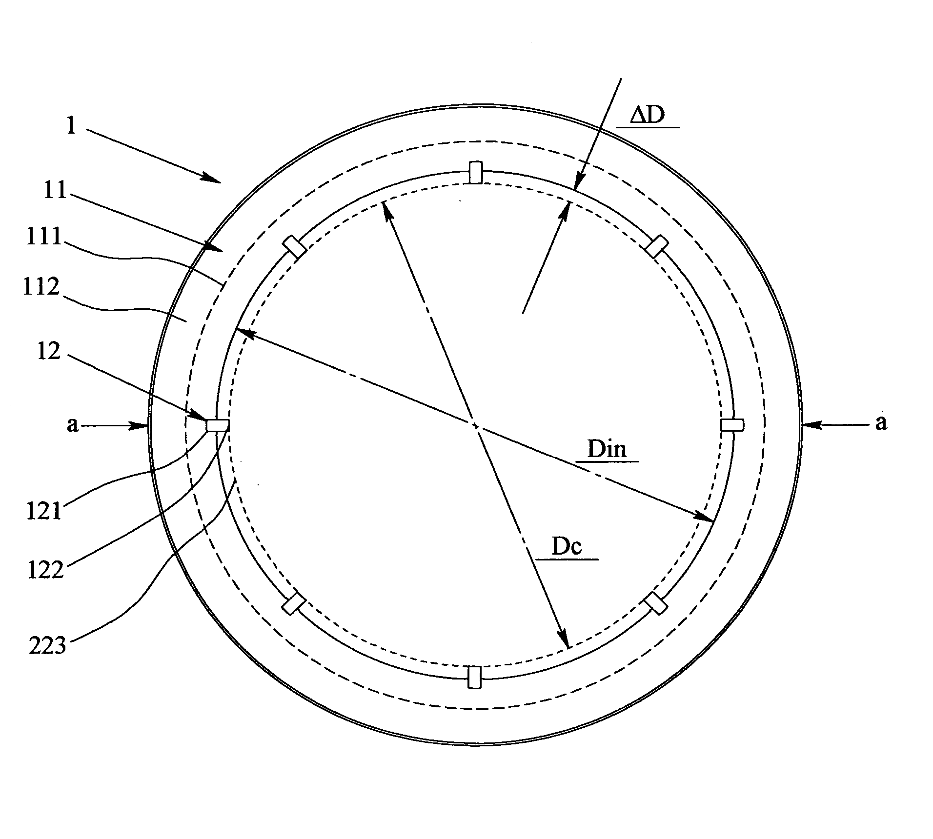
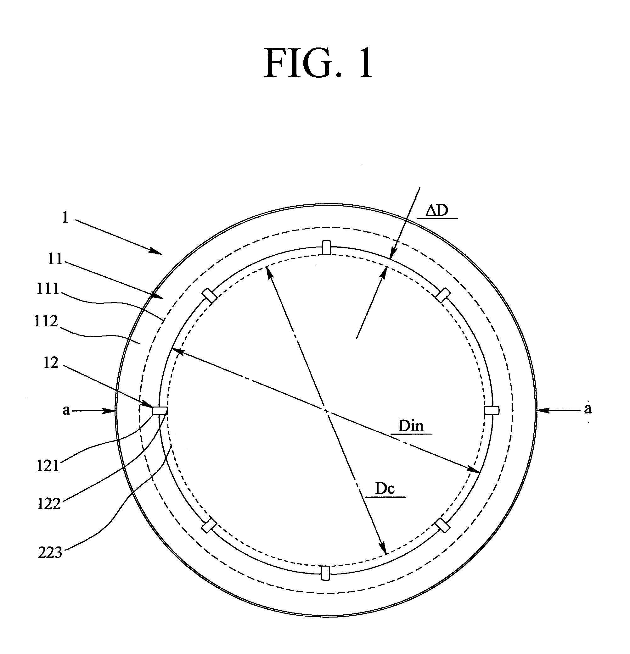
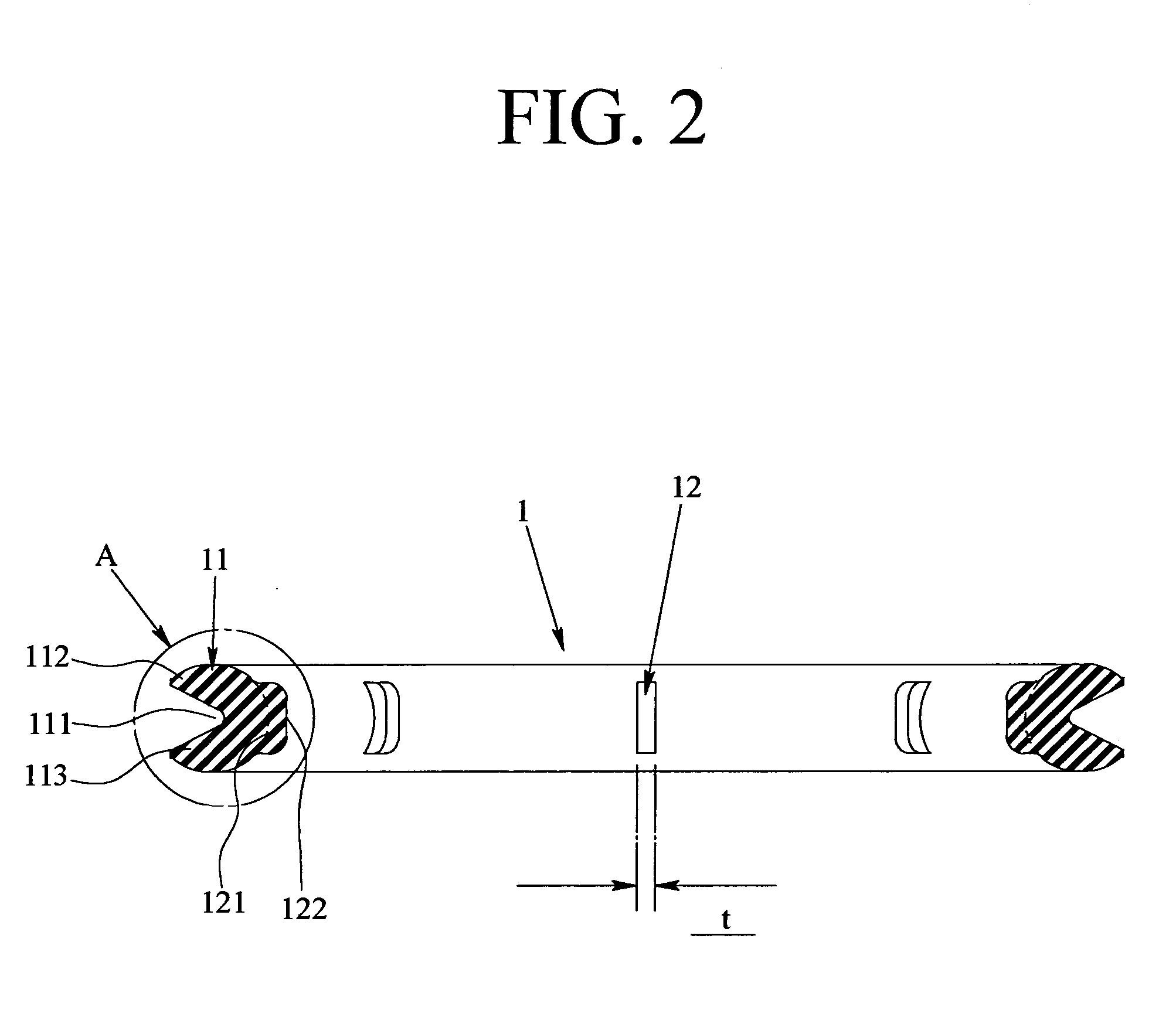
[0035] As shown in FIGS. 1 to 3, the seal ring 1 is molded of synthetic rubber integrally with: a ring body 11 of a C-shaped section having an upper and a lower lip portions 112,113 across a wedged circumference groove 111 on the outer circumference side thereof; and a plurality of vertical members 12 as the elastic ridge disposed...


PUM


Abstract

A fuel cap comprising a seal ring 1 mounted on a cap trunk portion 223 to realize liquid tightness and gas tightness, wherein the seal ring 1 includes a ring body 11 and an elastic support portion; the ring body 11 has a sizing relation between an external diameter Dc of the cap trunk portion 223 and an internal diameter Din of the ring body 11 which is Dc<Din, and has a C-shaped section formed by a wedged circumferential groove opening outward in radial direction of the ring; and the elastic support portion is a plurality of the elastic members 12,13,14,15,16 or one of the elastic flanges 17,18, or combination thereof, and disposed on the inner circumference side of the ring body 11 and protrudes with an amount of a radially inward protrusion d set at (Din−Dc) / 2 or greater.

Description

TECHNICAL FIELD [0001] The present invention relates to a fuel cap for closing the filler neck of a feed oil pipe extending from the fuel tank of an automobile or the like. BACKGROUND OF THE INVENTION [0002] The general fuel cap is constituted to have a seal ring mounted on a cap trunk portion to be inserted into a filler neck, for example, as disclosed in JP-A-2005-009661. This fuel cap realizes, when fastened on the filler neck, a liquid tightness and a gas tightness by pressing the seal ring onto a cap sealing face, such as the lower face of the upper flange and the filler neck sealing face of the cap trunk portion, such as the upper edge or the inner face of the filler neck. These liquid tightness and gas tightness are effectively exhibited when the central axis of the cap trunk portion is correctly aligned with the center of the seal ring. For this exhibition, the external diameter Dc of the cap trunk portion and the internal diameter Din of the ring body are held in a sizing r...

Claims


Application Information

Patent Timeline
Patent Type & Authority Applications(United States)
IPC IPC(8): B65D53/00
CPCB60K2015/0451B60K15/0406
Inventor YOSHIDA, HIROMITSU
Owner ASTEER
Learn More