Vehicle door structure

a technology for doors and vehicles, applied in the field of vehicle door structures, can solve the problems of permanent deformation generation, and achieve the effect of suppressing permanent deformation and increasing the build precision of the door to the vehicle body

Active Publication Date: 2008-01-10
TOYOTA JIDOSHA KK
View PDF18 Cites 19 Cited by
  • Summary
  • Abstract
  • Description
  • Claims
  • Application Information

AI Technical Summary

Benefits of technology

[0047] According to the present invention, as described above, permanent deformation of a door may be suppressed. By doing so, for example, the build precision of the door to vehicle body may be increased.

Problems solved by technology

There is a possibility of permanent deformation being generated, due to thermal distortion at the outer sheet portion of the door that is provided at the outer panel side, caused by the difference in the thermal expansion conditions between the door body side and the door panel side.

Method used


Image

  • Vehicle door structure
  • Vehicle door structure
  • Vehicle door structure

Examples


first embodiment

[0096] Explanation will now be given of a first exemplary embodiment of the present invention, with reference to FIG. 1 to FIG. 5.

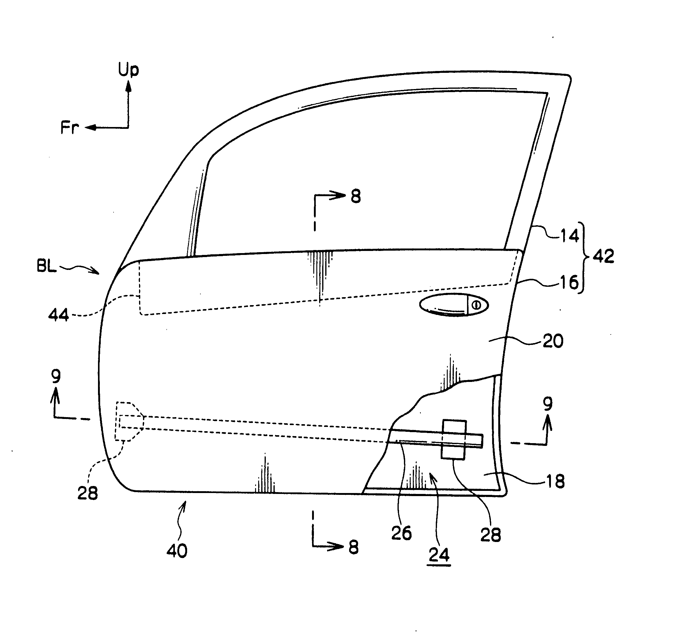
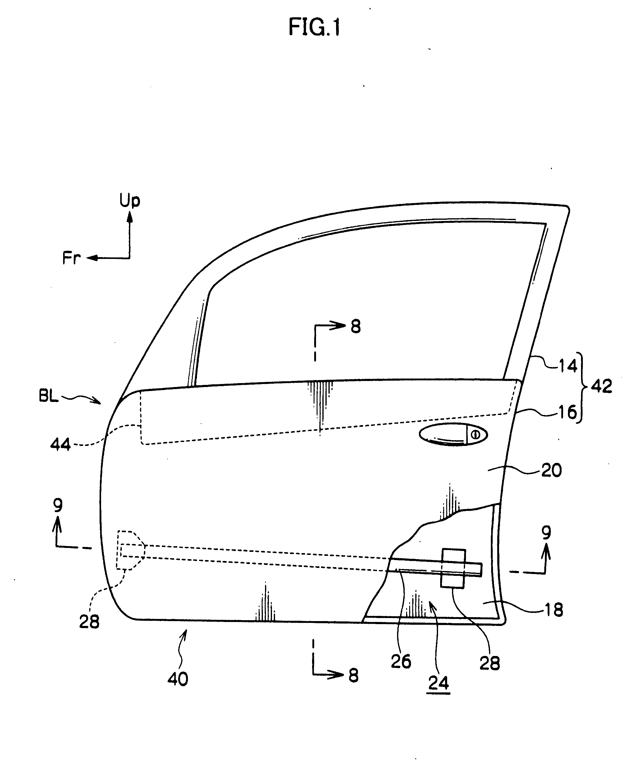
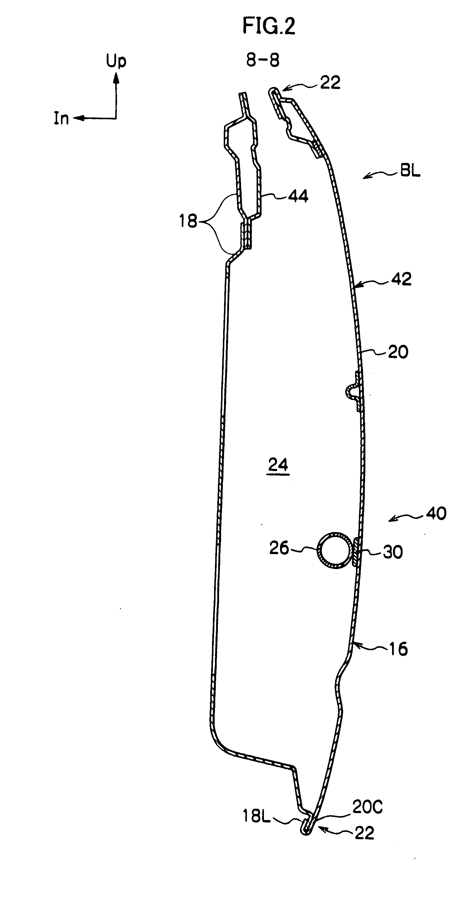
[0097]FIG. 1 to FIG. 3 are figures showing the structure of a door 42 to which the vehicle door structure 40 according to the first exemplary embodiment of the present invention is applied. In FIG. 4 and FIG. 5 are shown, in addition, examples of modifications to the vehicle door structure 40 according to the first exemplary embodiment of the present invention. In these diagrams, the arrow Fr indicates the vehicle front-rear direction front side, the arrow Up indicates the vehicle up-down direction up side, and the arrow In indicates the vehicle width direction inside.

[0098] The door 42 to which the vehicle door structure 40 according to the first exemplary embodiment of the present invention is applied is, for example, configured as a front side door of a vehicle such as a passenger car or the like. The door 42 is provided with a door frame 14 at the d...

second exemplary embodiment

[0124] Explanation will now be given of a second exemplary embodiment of the present invention, with reference to FIG. 6 to FIG. 12.

[0125] In FIG. 6 to FIG. 10 is shown a configuration of a door 52 to which a vehicle door structure 50 according to a second exemplary embodiment of the present invention is applied. In addition, FIG. 11 and FIG. 12 show examples of modifications to the vehicle door structure 50 according to the second exemplary embodiment of the present invention. In these figures, the arrow Fr indicates the vehicle front-rear direction front side, the arrow Up indicates the vehicle up-down direction up side, and the arrow In indicates the vehicle width direction inside.

[0126] The vehicle door structure 50 according to the second exemplary embodiment of the present invention is a vehicle door structure 40 according to the first exemplary embodiment of the present invention to which has been configured, as connecting portions, a front bracket 54, a lock reinforcement ...

third exemplary embodiment

[0159] Next, explanation will be given of the third exemplary embodiment of the present invention, with reference to FIG. 13 to FIG. 16.

[0160]FIG. 13 and FIG. 14 show a door 62 to which a vehicle door structure 60 according to the third exemplary embodiment of the present invention is applied. FIG. 15 andFIG. 16 show examples of modifications to the vehicle door structure 60 according to the third exemplary embodiment of the present invention. In these figures, the arrow Fr indicates the vehicle front-rear direction front side, the arrow Up indicates the vehicle up-down direction up side, and the arrow In indicates the vehicle width direction inside.

[0161] In the vehicle door structure 60 according to the present exemplary embodiment, is the vehicle door structure 50 according to the second exemplary embodiment of the present invention described above, to which a normal temperature curing adhesive 64 is applied at the join of the edge joint portions 22 of the door inner panel 18 a...


PUM


Abstract

A vehicle door structure for suppressing permanent deformation due to thermal distortion of a door is described. A door inner panel 18 and a door outer panel 20 are configured in aluminum alloy or the like. An impact beam 26 and a belt line inner reinforcement 44 are joined to the door inner panel 18. The impact beam 26 and the belt line inner reinforcement 44 are configured from a material, such as steel, with a smaller linear expansion coefficient than the door outer panel 20. Therefore, even if the door 42 as a whole is, for example, placed in a high temperature environment such as a bake oven in electrophoretic coating, the door inner panel 18 side and the door outer panel 20 side are restrained, respectively, by the belt line inner reinforcement 44 and the impact beam 26. Thus, permanent deformation due to thermal distortion at the door outer panel 20 side, due to a difference in the thermal expansion conditions of the door inner panel 18 side and the door outer panel 20 side, may be suppressed.

Description

CROSS-REFERENCE TO RELATED APPLICATION [0001] This application claims priority under 35 U.S.C. 119 from Japanese Patent Application No. 2006-161315, the disclosure of which is incorporated by reference herein. BACKGROUND OF THE INVENTION [0002] 1. Field of the Invention [0003] The present invention relates to a vehicle door structure, and in particular to a vehicle door structure configured with a door outer panel disposed at the outside of a door and a door inner panel disposed at the inside of the door. [0004] 2. Description of the Related Art [0005] Vehicle door structures are known, such as described in Japanese Patent Application (JP-A) Nos. 2004-314696, 2003-252057, and 2004-26070. In JP-A No. 2004-314696 an example of a vehicle door is described, with the door provided with main structures of a door body and an outer panel. The door body is formed as a substantially rectangular frame (skeleton structure), and the outer panel is fixed to the door body on the vehicle outside. F...

Claims


Application Information

Patent Timeline
Patent Type & Authority Applications(United States)
IPC IPC(8): B60J5/00
CPCB60J5/0426B60J5/0427B60J5/0483B60J5/0433B60J5/0431B60J5/00B60J5/04
Inventor ENDO, YOSHIHIDE
Owner TOYOTA JIDOSHA KK
Why Eureka
Try Eureka