
System and method for controlling velocity and detecting obstructions of a vehicle lift gate

a technology of vehicle lift gate and control system, which is applied in the direction of anti-hunting elements, position/direction control, ac motor stoppers, etc., can solve the problems of body part or physical object, damage or crushed, and vehicle parts or drive mechanisms that could be damaged, so as to improve the speed control

Active Publication Date: 2008-01-10
FLEXTRONICS AUTOMOTIVE
View PDF42 Cites 10 Cited by
  • Summary
  • Abstract
  • Description
  • Claims
  • Application Information

AI Technical Summary

Benefits of technology

[0005]To provide for improved speed control and obstacle detection of a rotational closure system, such as a lift gate, of a vehicle, the principles of the present invention provide for a direct sensing technique. The direct sensing technique senses an absolute position of the rotational closure system rather than sensing a motor or drive mechanism. In one embodiment, the system includes a motor having electrical contacts to receive drive signals and configured to move the rotational closure system of the vehicle between an open and a closed position in response to the drive signals. A controller may have electrical outputs electrically coupled to the electrical contacts of the motor and electrical inputs to receive feedback signals. The system may further include an angle sensor coupled to the rotational closure system and electrically coupled to the electrical inputs of the controller, where the controller generates a drive signal to drive the motor and the angle sensor generates an angle signal having a digital pulsewidth modulation form with a duty cycle based on the angle of the rotational closure system. The angle signal may be fed back to the controller via the electrical inputs of the controller and operable to cause the controller to alter the drive signal to change output of the motor while moving the rotational closure system between the open and closed positions. In one embodiment, the motor is a hydraulic pump. The controller may include a processor configured to determine if an obstacle is obstructing movement of the rotational closure system based on the angle signal.

Problems solved by technology

An obstacle, such as a body part or physical object, that obstructs a vehicle part while closing could be damaged or crushed, or the vehicle part or drive mechanism could be damaged, if the obstacle is not detected while the vehicle part is moving.
One problem with the use of Hall Effect sensors and optical vane interrupt sensors is a result of mechanical backlash due to system flex and unloaded drive mechanism conditions.
The obstacle detection process may take hundreds of milliseconds to complete, which is too long to detect a sudden movement of the lift gate and long enough to cause injury to a person or damage to an object, vehicle part, or drive mechanism.
As a result, obstacle detection is very difficult at the end of travel when sensitivity to obstacles should be the highest to avoid damaging obstacles or damaging the vehicle part.

Method used


Image

  • System and method for controlling velocity and detecting obstructions of a vehicle lift gate
  • System and method for controlling velocity and detecting obstructions of a vehicle lift gate
  • System and method for controlling velocity and detecting obstructions of a vehicle lift gate

Examples


Embodiment Construction

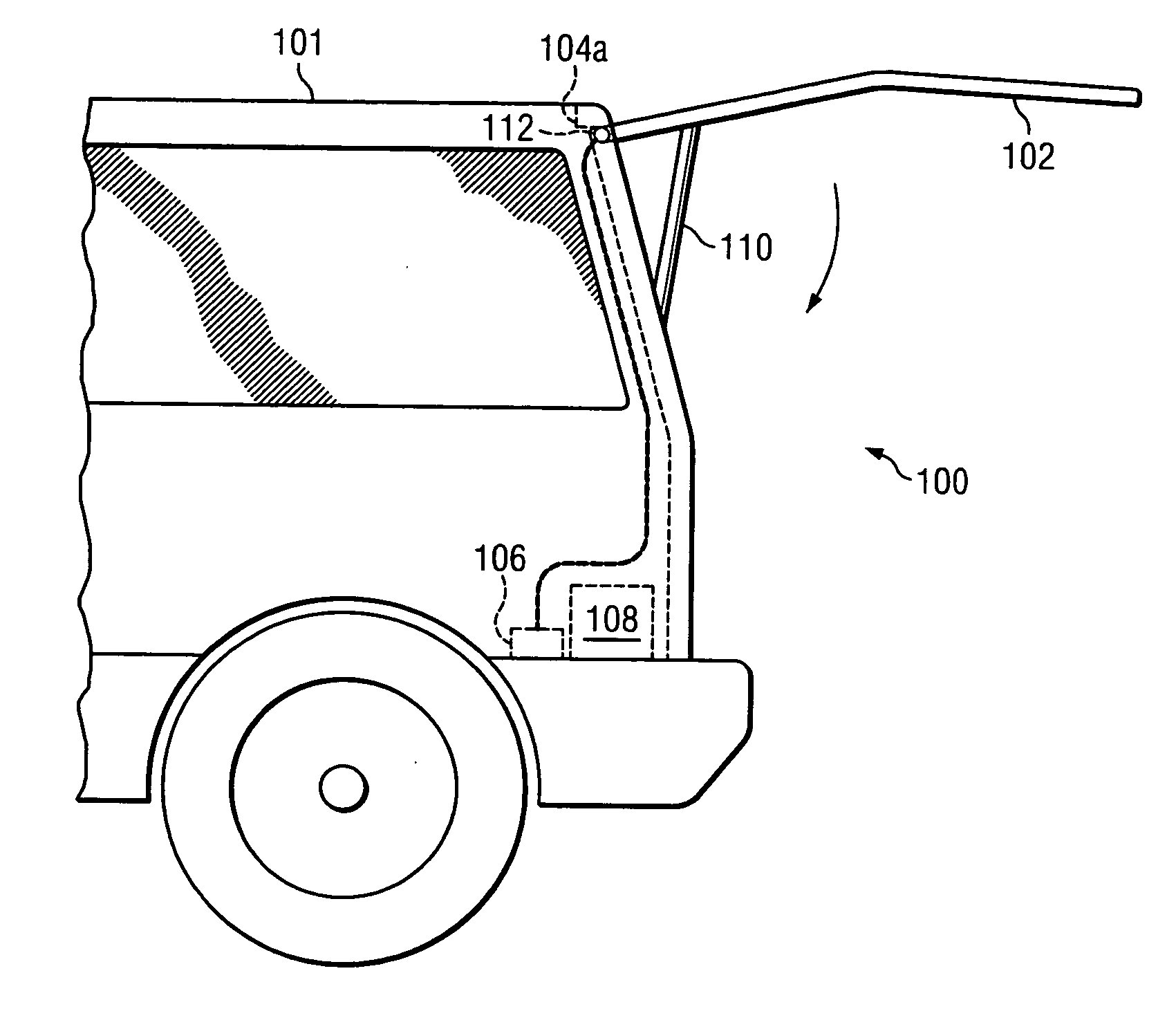
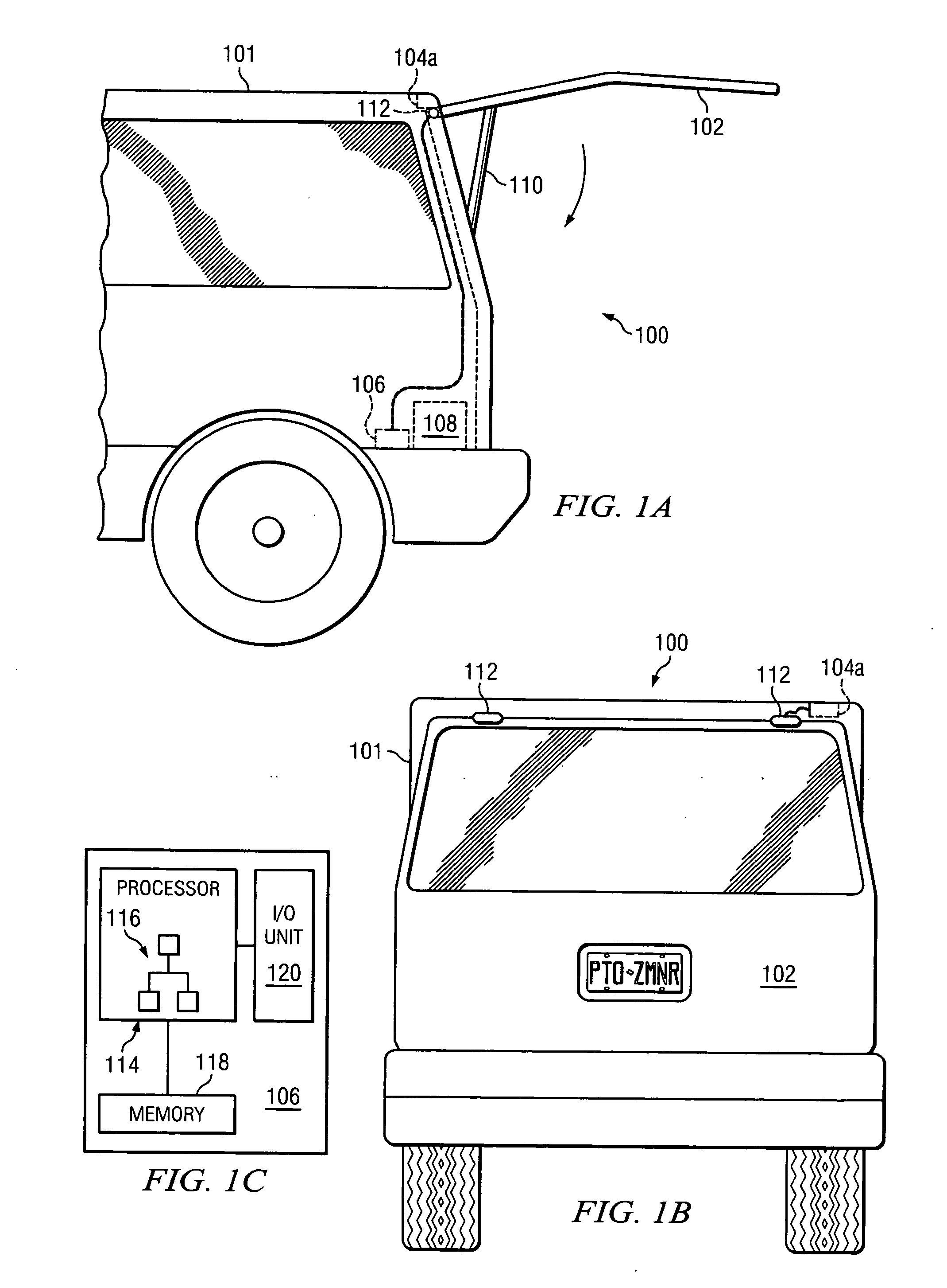
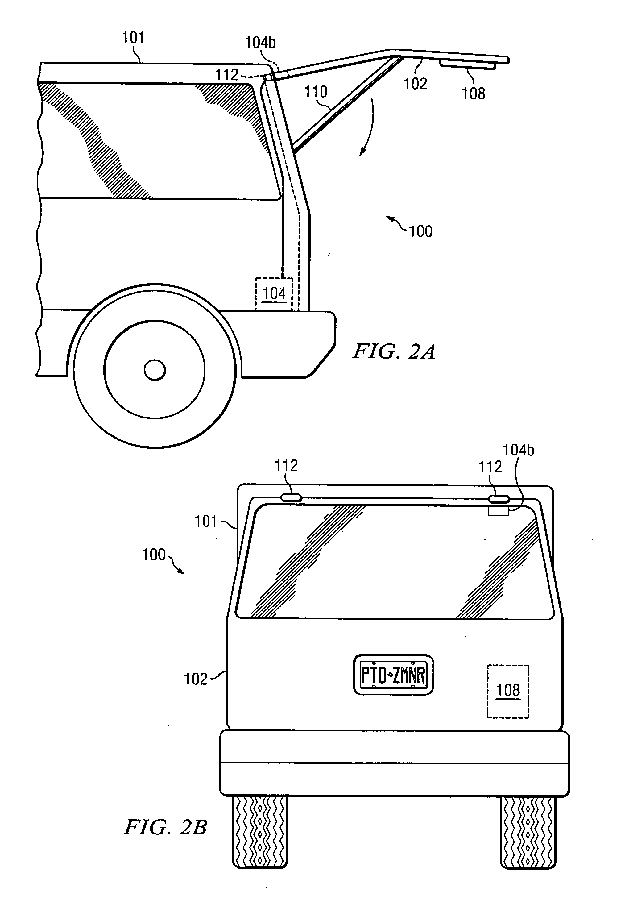
[0021]Direct measurement differs from indirect measurement in that direct measurement of a rotational closure system is derived from monitoring a signal that is produced by a sensor attached directly to the rotational closure system (e.g., lift gate) of the vehicle. The sensor may feed back a signal directly to a controller used to control the position and velocity of the lift gate and perform obstacle detection. The controller may further utilize the feedback signal to provide for increased obstacle detection sensitivity.

[0022]Moreover, direct measurement creates an intelligent system that knows the position of the rotational closure system being sensed regardless of the circumstances. Unlike the indirect incremental measurement that needs to establish its location at the beginning of operation, the direct measurement technique creates a knowledge of the rotational closure system location before, during, and after a move operation. This is accomplished by establishing an absolute p...


PUM


Abstract

A system and method for controlling a rotational closure system, such as a lift gate, of a vehicle may include sensing an angle of the rotational closure system, generating a drive signal, driving a drive mechanism with the drive signal to output a mechanical force for moving the rotational closure system, generating an angle signal having a digital pulsewidth modulation form with a duty cycle based on the angle of the rotational closure system, feeding back the angle signal, and, in response to the feedback angle signal, altering the drive signal while the drive mechanism is moving the rotational closure system between open and closed positions. In one embodiment, the angle signal is generated from a location disposed on the rotational closure system. A controller mounted to the rotational closure system may include an angle sensor and be configured to receive and process the angle signal to drive the drive mechanism.

Description

BACKGROUND OF THE INVENTION[0001]Vehicles have become more and more automated to accommodate the desires of consumers. Vehicle parts, including windows, sun roofs, seats, sliding doors, and lift gates (e.g., rear latches and trunks) have been automated to enable users to press a button on the vehicle or on a remote control to automatically open, close, or otherwise move the vehicle parts.[0002]While these vehicle parts may be automatically controlled, the safety of consumers and objects is vital. An obstacle, such as a body part or physical object, that obstructs a vehicle part while closing could be damaged or crushed, or the vehicle part or drive mechanism could be damaged, if the obstacle is not detected while the vehicle part is moving.[0003]In the case of detecting obstacles in the path of an automatic lift gate or other closure system, one conventional technique for speed control and sensing an obstacle has been to use Hall Effect sensors or optical vane interrupt sensors. The...

Claims


Application Information

Patent Timeline
Patent Type & Authority Applications(United States)
IPC IPC(8): H02P1/00
CPCE05Y2400/326E05Y2600/46E05F15/611E05Y2800/00E05Y2900/546
Inventor CHINSEN, JASONFROMMER, THOMAS P.DOMINIK, TOMASZ T.GRILLS, REGINALD C.
Owner FLEXTRONICS AUTOMOTIVE
Learn More