Incoming direction estimation apparatus

Inactive Publication Date: 2008-01-10
FUJITSU LTD
View PDF6 Cites 3 Cited by
  • Summary
  • Abstract
  • Description
  • Claims
  • Application Information

AI Technical Summary

Benefits of technology

[0019] The object for the present invention is to provide an incoming direction estimation apparatus capable of obtaining a wide field of view (FOV) and providing a high accuracy of angle measurement.
[0021] The present invention is contrived to reduce an apparent value range of tan−1(γ) included in an arithmetic expression used for estimating a direction by using signals from three (or more) sensors simultaneously and bring a necessary field of view into a zone where a calculation error is fundamentally small. This in turn makes it possible to widen an FOV per se.

Problems solved by technology

Too small an antenna interval, however, generates an electromagnetic coupling between the two antennas, losing an independence of two reception signals that are supposed to be obtained by essentially maintaining an exact phase difference indicated by the above expressions 1.1 and 1.2, and therefore an approximation represented by the expression 1.5 is no longer applicable even if Δy / Σy is forcibly transformed, resulting in making it difficult to estimate the θ accurately.
Meanwhile, a try to obtain a sufficient system gain needs to take a sufficient gain of the antennas, generally requiring a large area size for each antenna.
Consequently, a try to obtain a sufficient system gain makes the antennas become large, creating a situation of making it impossible to minimize the antenna interval.
The tan−1(γ), however, is a nonlinear function in which a derivative becomes smaller than “1” with a distance from the original point, and the nonlinearity of the tan−1(γ) further influences the sin−1 that is also a nonlinear function adversely to a large γ (i.e., to a signal incoming from an angle close to an FOV limit), thus resulting in fundamentally degrading accuracy of a measurement angle.
The apparatus, however, has a limited field of view (FOV) constrained by an absolute interval between the sensors and, moreover, a direction estimation error increases toward the edges of the FOV in terms of the primary value of an inverse triangular function.
Meanwhile, a try to increase the FOV is limited by a difficulty of setting individual sensors less than a certain interval due to the problem of physical size, gain or electromagnetic coupling of the individual sensors.
In this method, however, the FOV per se is still controlled by the absolute interval between the antennas, thus failing to provide a fundamental solution to the problem of the above paragraph 1.
Another problem is that an essential degradation of an accuracy of measurement angle cannot be avoided because it is basically a simple combination of two sets of conventional mono-pulse apparatuses.

Method used


Image

  • Incoming direction estimation apparatus
  • Incoming direction estimation apparatus
  • Incoming direction estimation apparatus

Examples


Embodiment Construction

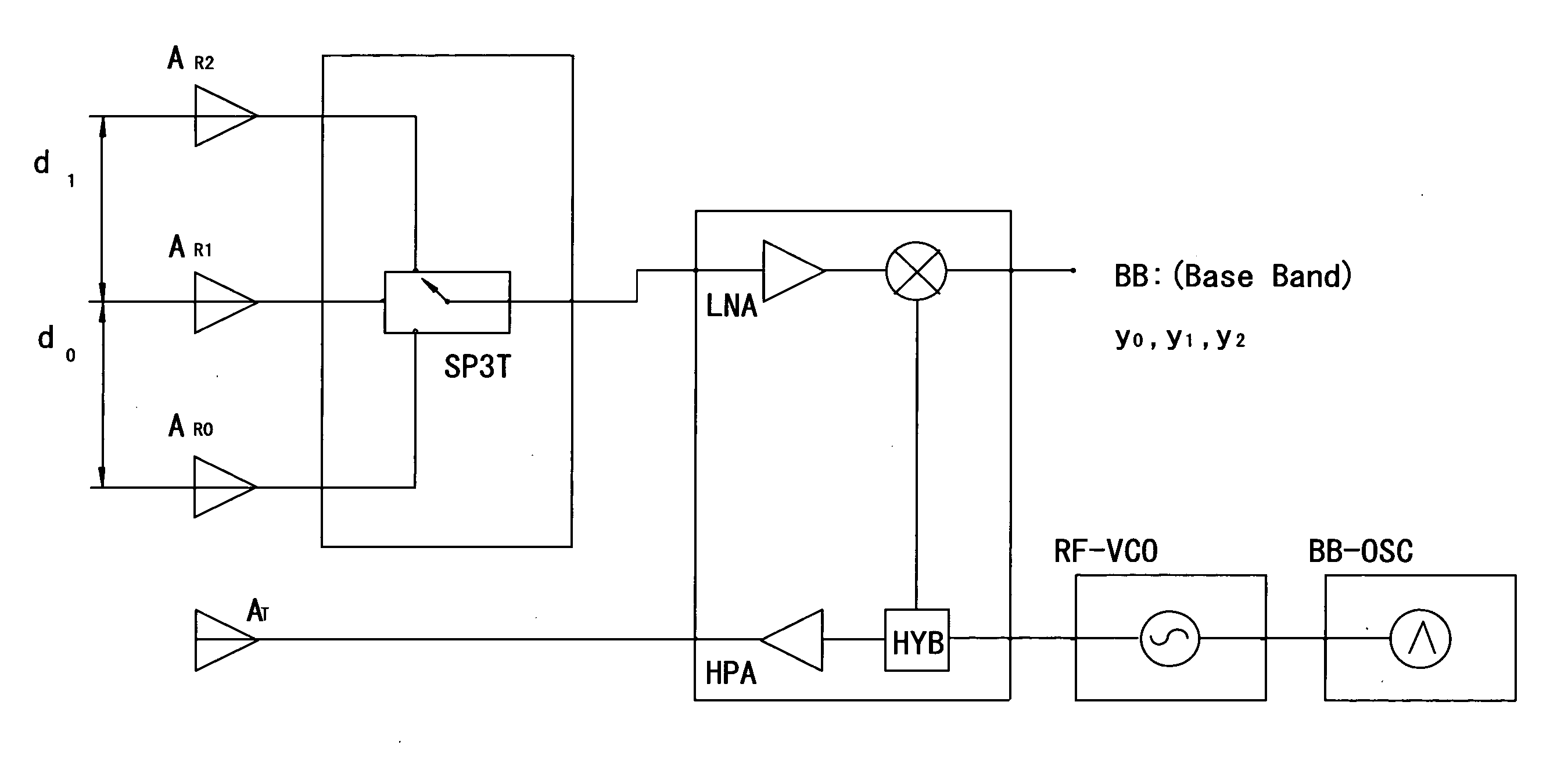
[0029] While the present invention is applicable to other incoming direction estimation apparatuses such as a sonar in lieu of a mono-pulse radar described above, a description herein exemplifies a mono-pulse radar in terms of a comparison of the conventional technique, and exemplifies the case of N=3, where N is the number of sensors.

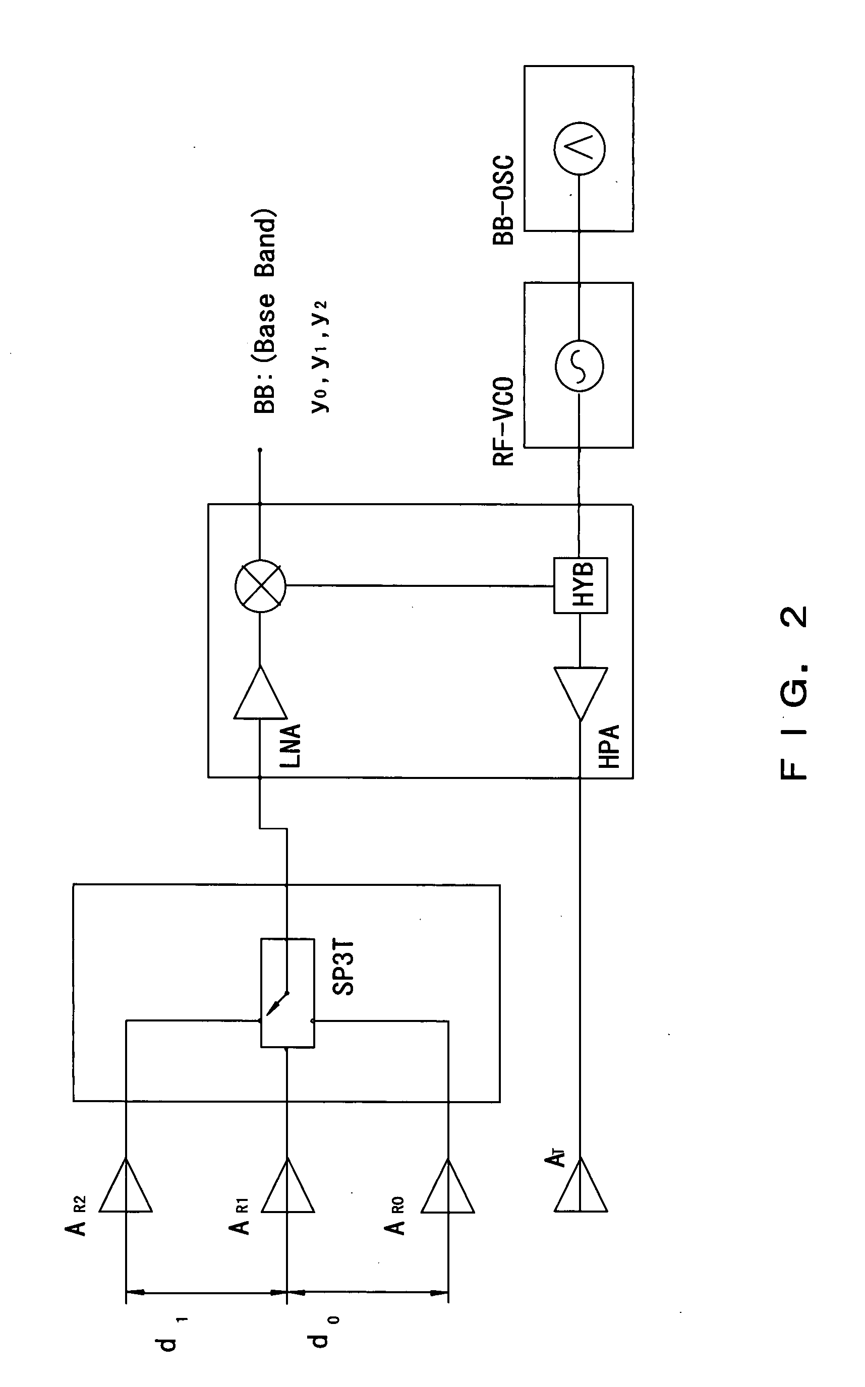
[0030]FIG. 2 is a diagram of an outline comprisal of a mono-pulse radar incoming direction estimation apparatus according to a preferred embodiment of the present invention.

[0031] In the showing of FIG. 2, the same component sign is assigned to the same constituent component as one shown in FIG. 1 and the description thereof is omitted here.

[0032] The configuration shown by FIG. 2 is equipped with three reception antennas. A switch SP3T (single-pole, 3-throw) changes over radar wave reception signals from the three antennas sequentially and transmits them to a later stage.

[0033] Where defining antenna intervals of three antennas (A0, A1 and A2) as:...


PUM


Abstract

An incoming direction estimation apparatus estimates an incoming direction of a radar wave using three or more sensors or antennas simultaneously. An arithmetic expression for estimating an incoming direction of a radar wave is configured as sin−1((½πa)*tan−1b). The “a” is d / λ determined by an antenna interval and by a wavelength λ of a carrier, or such, carrying the radar wave. A simultaneous use of three antennas makes it possible to set the a as a value depending on a value d0=a0λ based on the interval between first antennas and value d1=a1λ based on the interval between second antennas. Therefore, if a wide field of vision of an incoming direction is needed, it is only necessary to adjust (d1−d0) / λ=(a1−a0), in place of the absolute interval of antennas a=d / λ, thereby making it possible to lessen a limitation on the design of antennas and set a field of vision of the incoming direction appropriately.

Description

CROSS REFERENCE TO RELATED APPLICATION [0001] This application is a continuation of international PCT application No. PCT / JP2005 / 002448 filed on Feb. 17, 2005.BACKGROUND OF THE INVENTION [0002] 1. Field of the Invention [0003] The present invention relates to an incoming direction estimation apparatus. [0004] 2. Description of the Related Arts [0005]FIG. 1 is a diagram showing a mono-pulse radar as an example of a conventional incoming direction estimation apparatus. [0006] This apparatus is a system comprising one transmission antenna AT, two reception antennas AR0 and AR1, an interface module (this comprisal adopts a single-pole, double-throw (SPDT)), which interfaces the reception antennas, and a radio frequency (RF) unit, an RF unit constituted by a transceiver and receiver, an RF oscillator, a base band (BB) oscillator, a BB module (not shown herein) comprising an analog to digital (A / D) converter, et cetera, and a signal processing apparatus (also not shown herein) comprising ...

Claims


Application Information

Patent Timeline
IPC IPC(8): G01S5/04
CPCH01Q21/06G01S13/44
Inventor SHIRAKAWA, KAZUO
Owner FUJITSU LTD
Why Eureka
Try Eureka