Auto-stereoscopic diffraction optics imaging system providing multiple viewing pupil pairs

Inactive Publication Date: 2008-01-10
MOSS GAYLORD E
View PDF3 Cites 13 Cited by
  • Summary
  • Abstract
  • Description
  • Claims
  • Application Information

AI Technical Summary

Benefits of technology

[0009]This disclosure teaches a method to make an autostereoscopic imaging system which has the advantages of Newswanger but that allows multiple observers to see the display without the need for an additional pair of projectors for each observer. Only a single pair of projectors is needed for any number of observers; the allowable number of observers is mainly limited by the space available in front of the screen. Larger screens can accommodate more observing positions.
[0010]The imaging system of the present disclosure, when made as a transmission imaging system, employs a diffraction optical element that includes the holographic image of a diffuse pupil area constructed with a reference beam that converges to a point. The diffraction optical element is used as a display screen by projecting an image onto the diffraction optical element from the point of convergence of the constructing reference beam. The image-forming projection beam becomes a reversed reference beam forming a real image of the diffuse viewing pupil area that was holographically recorded. The effect is that the light from any point on the diffraction optical element is spread over the area of the diffuse screen real image. Since the diffraction optical element illumination is the image that is projected on it, the result is that an observer's eye anywhere in the real diffuser image area will see the full image projected on the screen diffracted into that area. Outside of the image screen area, there is no diffracted image. The autostereoscopic display is created by using two projectors to focus both the left and right eye images onto the d

Problems solved by technology

For long-term use, such viewing attachments may cause discomfort and fatigue.
These systems all lose at least half of the available image resolution in displaying both images.
In addition, as the user moves out of a limited viewing area, the images are sent to the opposite eyes, reversing the depth of the image, which is very disturbing to the user.
This system provides autostereoscopic viewing for one viewer with the limitation that the vie

Method used


Image

  • Auto-stereoscopic diffraction optics imaging system providing multiple viewing pupil pairs
  • Auto-stereoscopic diffraction optics imaging system providing multiple viewing pupil pairs
  • Auto-stereoscopic diffraction optics imaging system providing multiple viewing pupil pairs

Examples


Example

[0024]Embodiments of the presently disclosed imaging system will be described below with reference to the accompanying drawing figures wherein like reference numerals identify similar or identical elements. In the following description, well-known functions or constructions are not described in detail to avoid obscuring the disclosure in unnecessary detail.

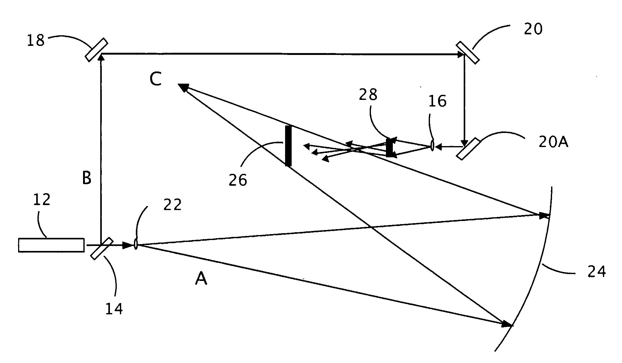
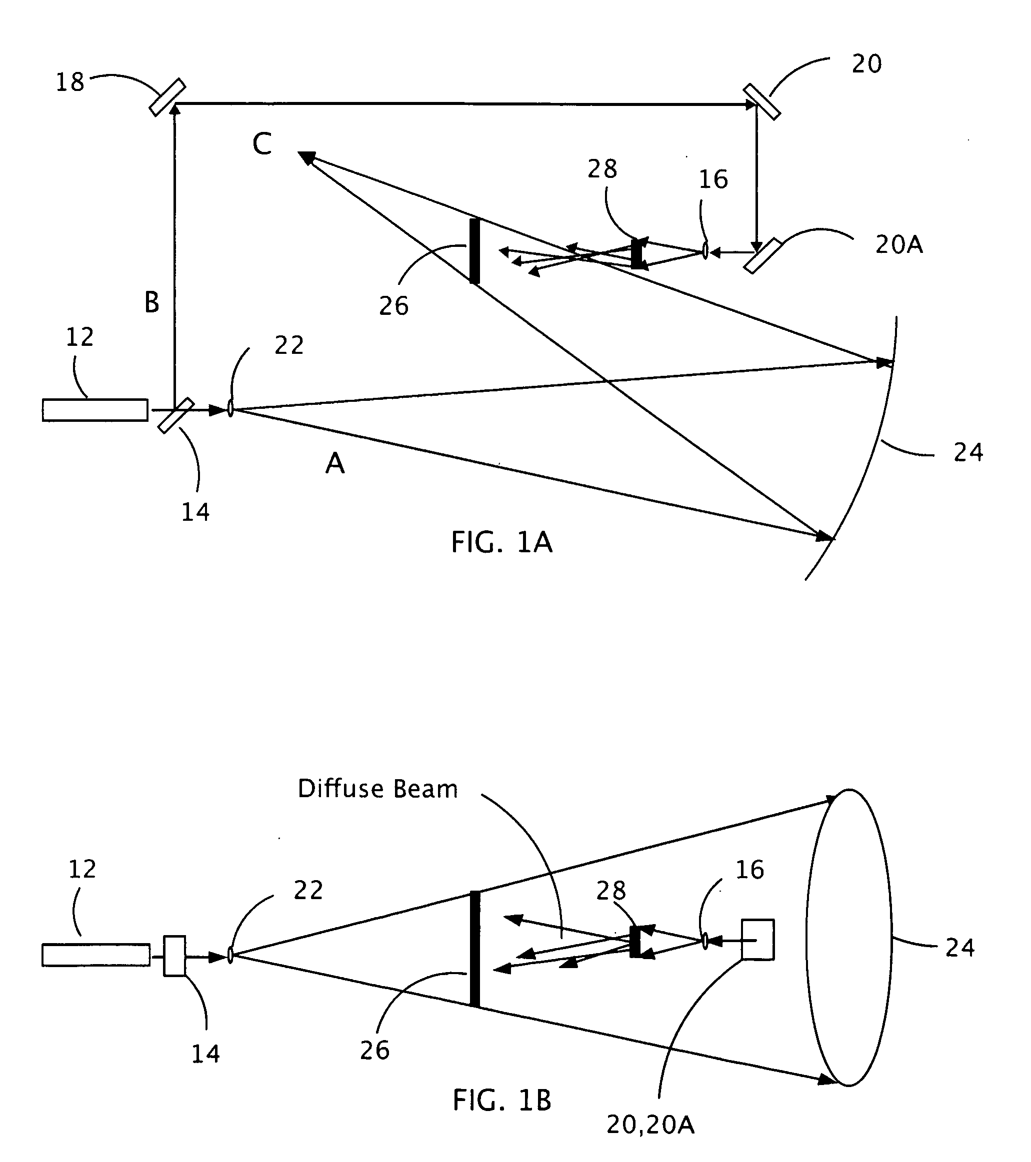
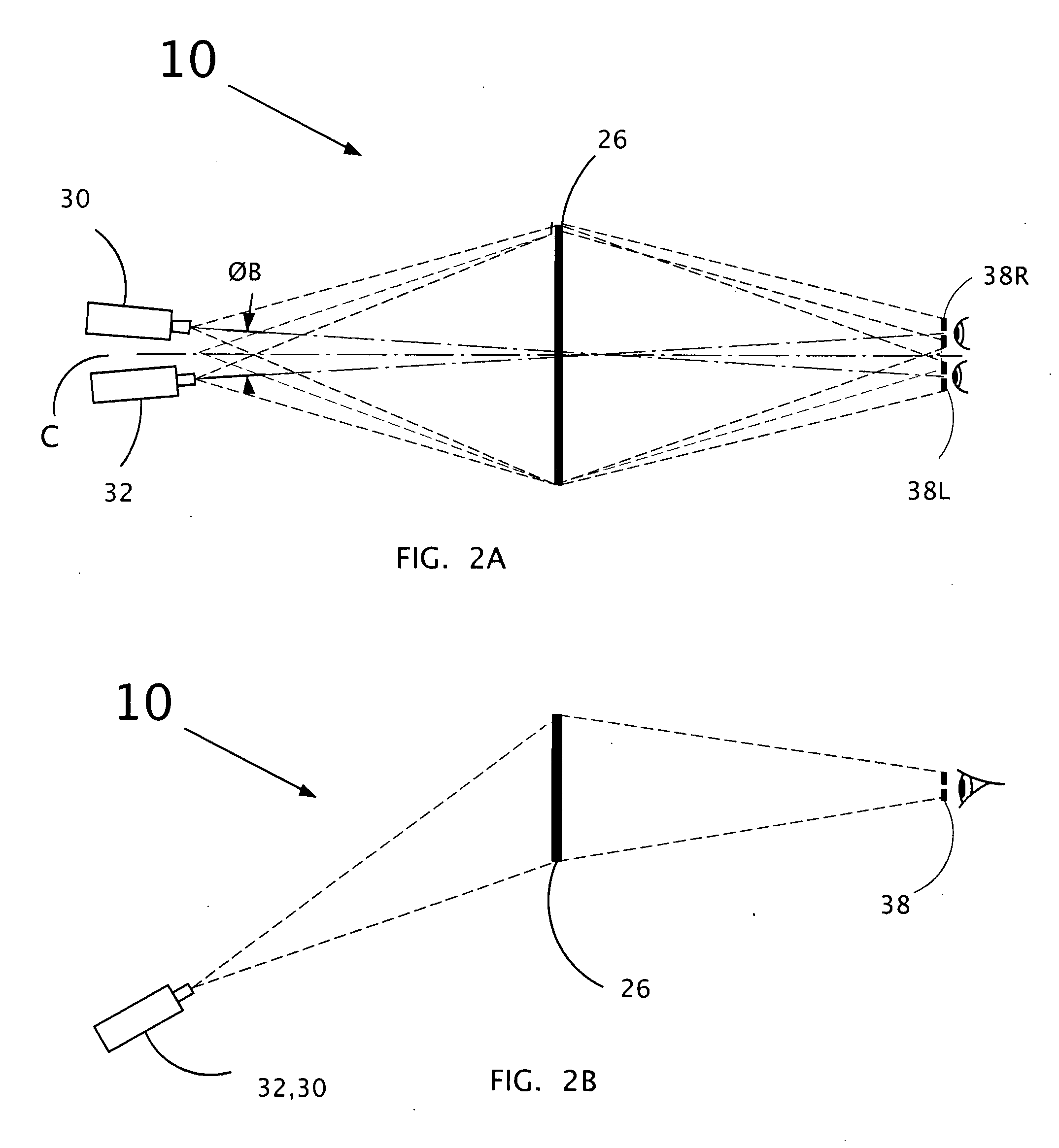
[0025]This disclosure describes an autostereoscopic imaging system 10 for showing a three dimensional image. One embodiment makes use of multiple transmission holographic images of separate diffusers which are combined to form a diffraction optics imaging system. FIGS. 1A and 1B show top and side views, respectively, of an optical setup for recording one diffuser 28 into a holographic recording plate 26 that may be processed, as necessary or appropriate, to form a diffraction optical element 26 (see FIG. 2A). As shown in FIG. 1A, the beam from laser 12 is split by beam splitter 14 with one of the resulting beams (B) directed by mi...


PUM


Abstract

An autostereoscopic imaging system is disclosed that provides for a three dimensional display of an image to multiple observers simultaneously from a single pair of stereoscopic projectors. The system provides for high quality immersive imagery using a holographic diffractive optical element that is made and configured to contain multiple holograms of optical diffusers, each of the holograms having a common reference beam and being made with each diffuser in a different location. A pair of projectors placed astride the reference beam virtual focus projects a stereoscopic image onto the diffractive optical element, such that the plurality of holograms reconstructs multiple stereoscopic images at multiple locations corresponding to the location where the diffusers were previously located during the recording of each respective hologram. Methods of making the diffractive optical element with a plurality of holograms are also disclosed. The holograms may be made on separate plates and laminated together, or may be made by simultaneous, sequential, or repeated partial sequential exposures onto a single holographic plate.

Description

BACKGROUND[0001]1. Technical Field[0002]The present disclosure describes a system for a three dimensional display for multiple observers, and, in particular, a system that provides stereo imagery for multiple observers without the need for special glasses or goggles.[0003]2. Description of the Related Art[0004]Stereoscopic imaging systems are well known in the art. Many stereoscopic imaging systems require the user to wear a device in order to view a stereoscopic image. Such devices enable the user to see a different image with each eye so that the user perceives depth from the disparate images seen by both eyes. For long-term use, such viewing attachments may cause discomfort and fatigue.[0005]There are well-known stereo display techniques better suited to long-term use because they do not require the wearing of any attachments. Such displays are called autostereoscopic. One such is the well-known use of lenticular molded lenses in a sheet such as is used in postcards to show stere...

Claims


Application Information

Patent Timeline
IPC IPC(8): G03H1/04
CPCG02B5/0252G02B5/32G02B27/225H04N13/0459G03H2001/0439G03H2222/34H04N13/0402G03H1/26H04N13/302H04N13/363
Inventor MOSS, GAYLORD E.
Owner MOSS GAYLORD E
Why Eureka
Try Eureka