Scalable magnetic random access memory device

a random access and memory device technology, applied in the field of data storage, to achieve the effect of reducing the switching field

Active Publication Date: 2008-01-10
IBM CORP
View PDF3 Cites 0 Cited by
  • Summary
  • Abstract
  • Description
  • Claims
  • Application Information

AI Technical Summary

Benefits of technology

[0006]The present invention provides techniques for reducing the switching fields in magnetic memory devices. In one aspect of the invention, a magnetic memory cell is provided. The magnetic memory cell comprises at least one fixed magnetic layer and a plurality of free magnetic layers, separated from the at least one fixed magnetic layer by at least one barrier layer. The free magnetic layers include a first free magnetic layer adjacent to the barrier layer, a second free magnetic layer separated from the first free magnetic layer by at least one spacer layer, and a third free magnetic layer separated from the second free magnetic layer by at least one anti-parallel coupling layer. A magnetic moment of the first free magnetic layer is greater than both a magnetic moment of the second free magnetic layer and a magnetic moment of the third free magnetic layer.

Problems solved by technology

Both of these approaches, however, are prone to the problems associated with scaling that are described above.

Method used


Image

  • Scalable magnetic random access memory device
  • Scalable magnetic random access memory device
  • Scalable magnetic random access memory device

Examples


Embodiment Construction

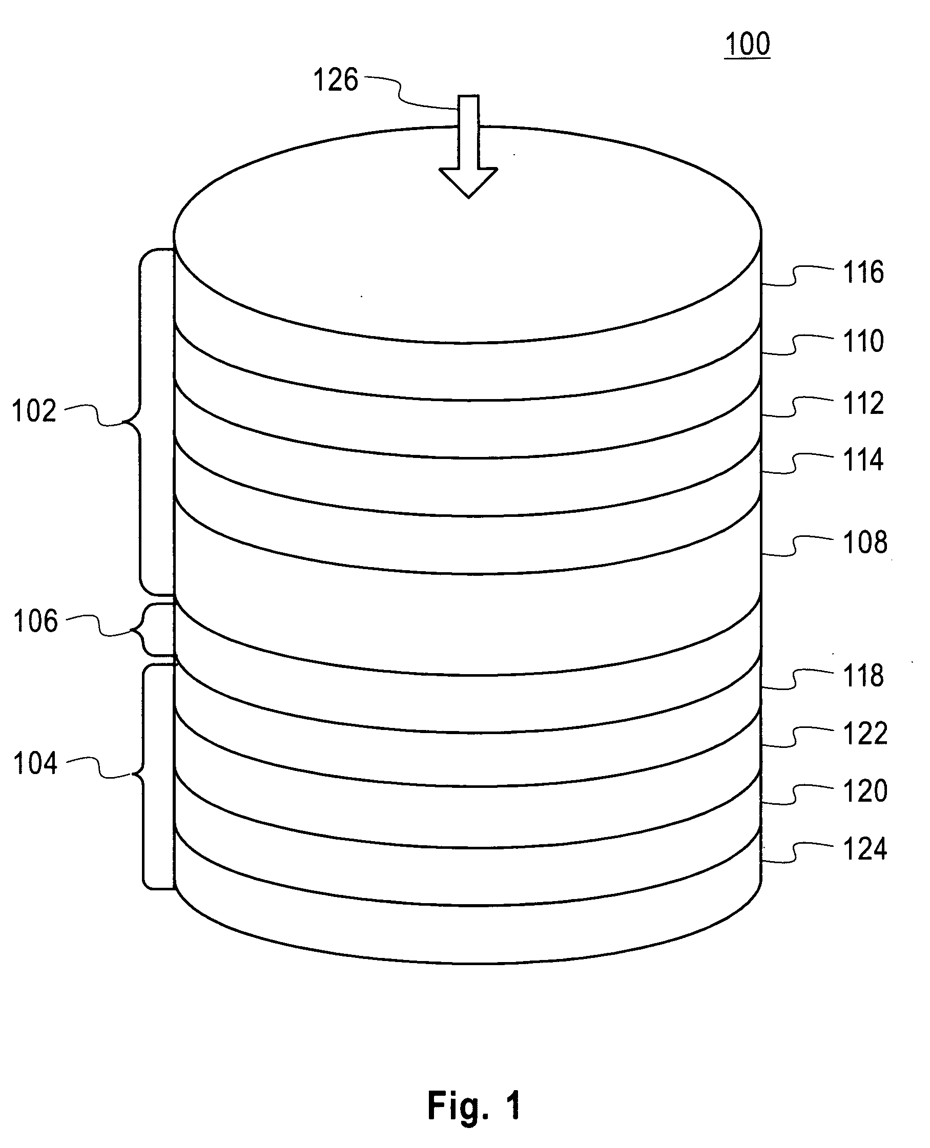
[0022]FIG. 1 is a diagram illustrating exemplary magnetic memory cell 100. Magnetic memory cell 100 comprises tunnel barrier 106 deposited on fixed layer 104, and free layer 102 deposited on tunnel barrier 106.

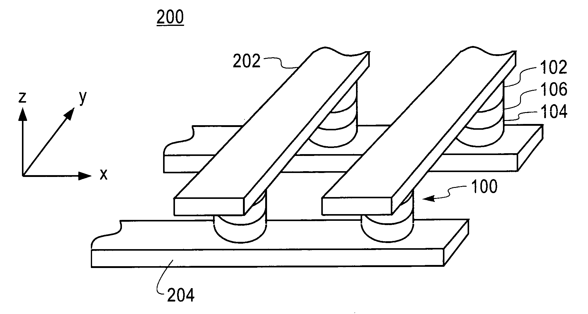
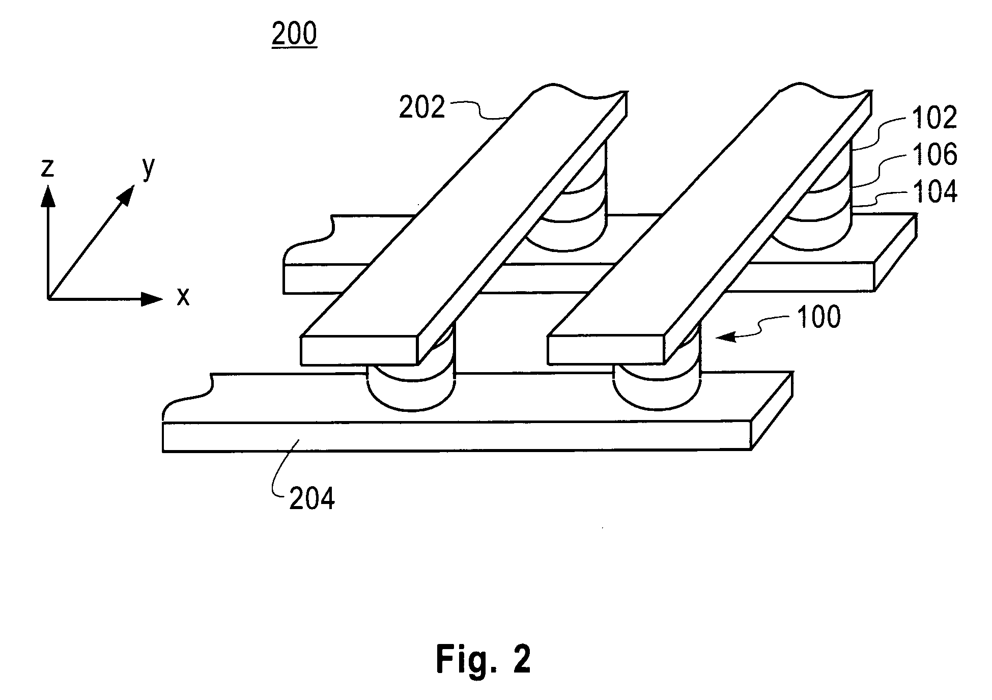
[0023]According to the exemplary embodiment depicted in FIG. 1, magnetic memory cell 100 can be configured, i.e., patterned, to have, when viewed from top-down view 126, a circular (or elliptical) shape. See also the top-down depictions of magnetic memory cell 100 having a circular shape in FIGS. 3A-B, described below. It is to be understood, however, that any other patternable shapes and / or configurations can be employed in accordance with the present teachings. As will be described in detail below, magnetic memory cell 100 may be used in conjunction with a magnetic random access memory (MRAM) device.

[0024]As shown in FIG. 1, free layer 102 is a multiple-layer structure. Namely, free layer 102 comprises magnetic layer 108 adjacent to tunnel barrier 106. Spacer layer 114 is de...


PUM


Abstract

Techniques for data storage are provided. In one aspect, a magnetic memory cell is provided. The magnetic memory cell comprises at least one fixed magnetic layer and a plurality of free magnetic layers, separated from the at least one fixed magnetic layer by at least one barrier layer. The free magnetic layers include a first free magnetic layer adjacent to the barrier layer, a second free magnetic layer separated from the first free magnetic layer by at least one spacer layer, and a third free magnetic layer separated from the second free magnetic layer by at least one anti-parallel coupling layer. A magnetic moment of the first free magnetic layer is greater than both a magnetic moment of the second free magnetic layer and a magnetic moment of the third free magnetic layer.

Description

FIELD OF THE INVENTION[0001]The present invention relates to data storage, and more particularly, to data storage devices and techniques for use thereof.BACKGROUND OF THE INVENTION[0002]Semiconductor devices, such as magnet random access memory (MRAM) devices, use magnetic memory cells to store information. Information is stored in the magnetic memory cells as an orientation of the magnetization of a free layer in the magnetic memory cell as compared to an orientation of the magnetization of a fixed (e.g., reference) layer in the magnetic memory cell. The magnetization of the free layer can be oriented parallel or anti-parallel relative to the fixed layer, representing either a logic “1” or a logic “0.” The orientation of the magnetization of a given layer (fixed or free) may be represented by an arrow pointing either to the left or to the right. When the magnetic memory cell is sitting in a zero applied magnetic field, the magnetization of the magnetic memory cell is stable, pointi...

Claims


Application Information

Patent Timeline
Patent Type & Authority Applications(United States)
IPC IPC(8): G11C11/00
CPCG11C11/16
Inventor WORLEDGE, DANIEL C.
Owner IBM CORP
Why Eureka
Try Eureka