
Magnetic random access memory with lower switching field through indirect exchange coupling

Inactive Publication Date: 2006-06-29
IND TECH RES INST
View PDF2 Cites 7 Cited by
  • Summary
  • Abstract
  • Description
  • Claims
  • Application Information

AI Technical Summary

Benefits of technology

[0012] According to object of the invention, the magnetic random access memory with lower switching field through indirect exchange coupling may reduce the switching field of the ferromagnet free layer.
[0013] According to the embodiment of the invention, the magnetic random access memory with lower switching field through indirect exchange coupling may reduce write current when writing data into the memory cell.
[0018] According to the embodiment of the invention, the magnetic random access memory with lower switching field through indirect exchange coupling has the advantage of reducing the switching field of the ferromagnetic free layer.
[0019] According to the embodiment of the invention, the magnetic random access memory with lower switching field through indirect exchange coupling has the advantage of reducing write current.
[0020] According to the embodiment of the invention, few modifications are made in the manufacturing process for the magnetic random access memory with lower switching field. Thus, the manufacturing process may integrate with the original process for the magnetic random access memory, and the switching field is effectively reduced.

Problems solved by technology

The large current makes the circuit design or the driver circuit design more difficult.
Although this method can reduce the switching field of the ferromagnetic free layer, the switching behavior of the magnetization of the ferromagnetic free layer becomes very complicated.
However, it has a limited effect in terms of lowering the switching field of the ferromagnetic free layer.
This imposes some difficulty in circuit designs.

Method used


Image

  • Magnetic random access memory with lower switching field through indirect exchange coupling
  • Magnetic random access memory with lower switching field through indirect exchange coupling
  • Magnetic random access memory with lower switching field through indirect exchange coupling

Examples


Embodiment Construction

[0026] Reference will now be made in greater detail to a preferred embodiment of the invention, an example of which is illustrated in the accompanying drawings. Wherever possible, the same reference numerals are used throughout the drawings and the description to refer to the same or like parts. Reference in the specification to “one embodiment” or “an embodiment” means that a particular feature, structure, or characteristic described in connection with the embodiment is included in at least one embodiment of the invention. The appearances of the phrase “in one embodiment” in various places in the specification are not necessarily all referring to the same embodiment.

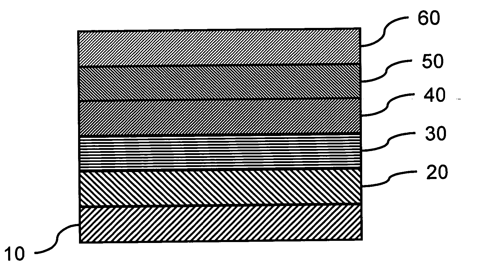
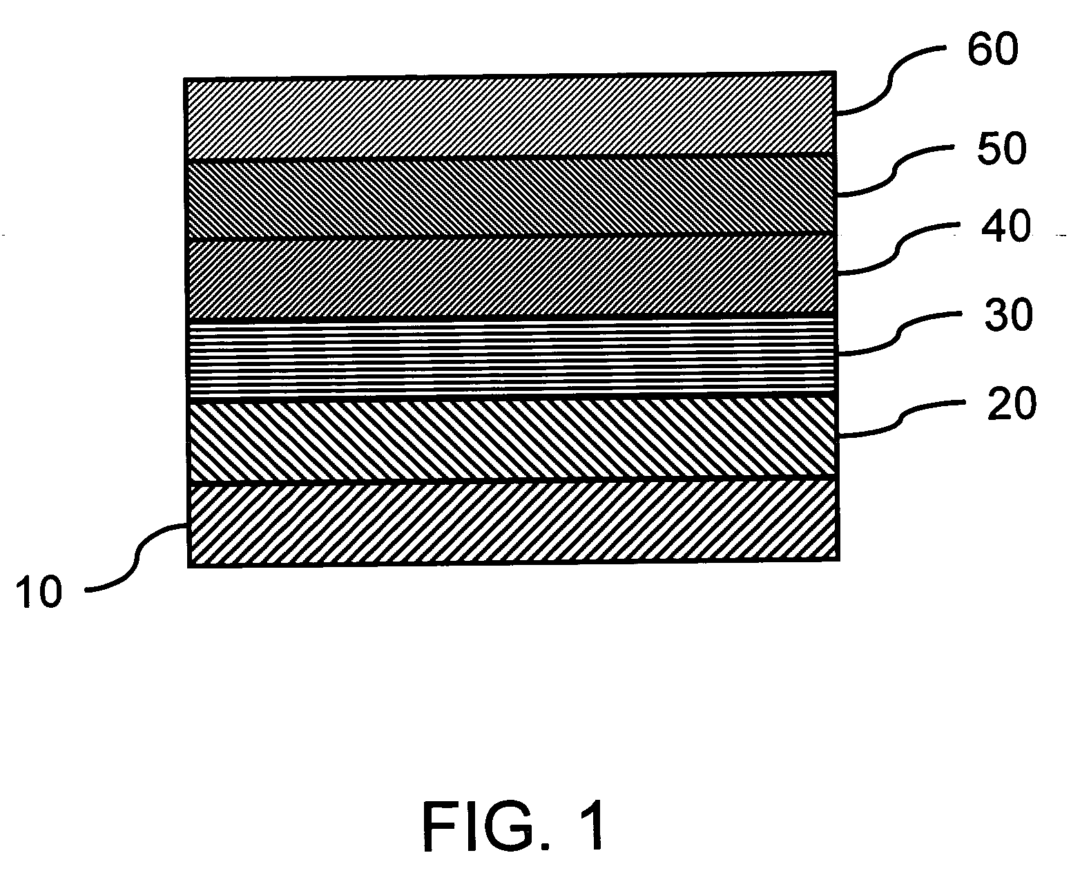
[0027]FIG. 1 shows the simplified cross-sectional view of a typical MRAM. The drawing also shows a single MRAM (or memory cell). The actual MRAM array can be composed of several MRAM's shown in FIG. 1.

[0028] The magnetic memory includes a first antiferromagnetic layer 10, a pinned layer 20 formed on the first antiferr...


PUM


Abstract

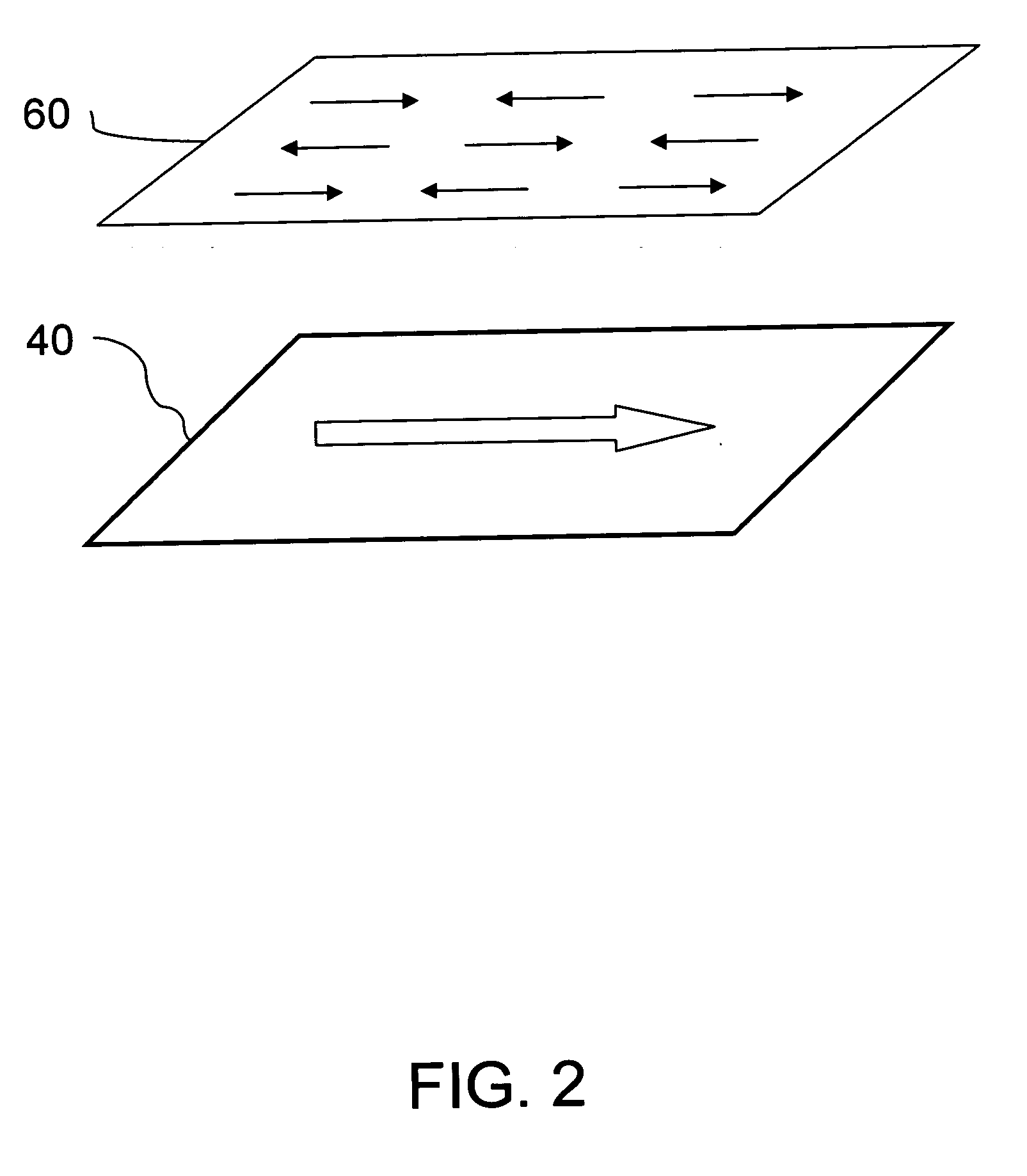
A magnetic random access memory with lower switching field through indirect exchange coupling. The memory includes a first antiferromagnetic layer, a pinned layer formed on the first antiferromagnetic layer, a tunnel barrier layer formed on the pinned layer, a ferromagnetic free layer formed on the tunnel barrier layer, a metal layer formed on the ferromagnetic free layer, and a second antiferromagnetic layer formed on the metal layer. The anisotropy axis of the second antiferromagnetic layer and the ferromagnetic layer and that of the ferromagnetic free layer are arranged in parallel. The net magnetic moment of the antiferromagnetic layer interface between the second antiferromagnetic layer and the metal layer is close to zero. The memory has the advantages of lowering the switching field of the ferromagnetic layer and lowering the writing current.

Description

[0001] This application claims the benefit of Taiwan Patent Application No. 9,314,1242, filed on Dec. 29, 2004, which is hereby incorporated by reference for all purposes as if fully set forth herein. BACKGROUND [0002] 1. Field of Invention [0003] The invention relates to a magnetic random access memory, and in particular to a magnetic random access memory that has a lower switching field in the ferromagnetic free layer and power consumption. [0004] 2. Related Art [0005] The magnetic random access memory (MRAM) is a type of nonvolatile memory. It utilizes magnetoresistance properties to record information and has the advantages of non-volatility, high density, high read / write speed, and anti-radiation. When writing data, a general method is to use the intersection of the induced magnetic fields of two circuit lines, the bit line and the write word line, to select a cell. Resistance is modified by changing the magnetization of a ferromagnetic free layer. When the MRAM reads recorded ...

Claims


Application Information

Patent Timeline
IPC IPC(8): H01L27/108
CPCB82Y25/00G11C11/16H01F10/3254H01F10/3281H01L43/08H10N50/10
Inventor LEE, YUAN-JENWANG, YUNG-HUNGWANG, LIEN-CHANGKAO, MING-JER
Owner IND TECH RES INST
Learn More