Quench protection of HTS superconducting magnets

a superconducting magnet and quench protection technology, applied in the field of superconducting magnets, can solve the problems of discharge of magnets, discharging of magnets, and magnet to a mode of failure, and achieve the effect of effective quench protection, improved active protection of superconducting coils, and reduced circuit breaker switch voltag

Inactive Publication Date: 2006-12-28
FLORIDA STATE UNIV RES FOUND INC
View PDF23 Cites 60 Cited by
  • Summary
  • Abstract
  • Description
  • Claims
  • Application Information

AI Technical Summary

Benefits of technology

[0020] Embodiments of the invention overcome one or more deficiencies in the prior art by providing improved active protection of superconducting coils during quench. Aspects of the invention address the lack of rapid normal zone propagation, which is a fundamental difficulty in the quench protection of HTS coils and, thus, are particularly well suited to protection of such coils. Advantageously, a multiplicity of heaters distributed throughout the windings of a superconducting coil permits the distribution of normal regions during quench without relying on a rapid natural propagation of the normal zone by the conductor. The construction of coils with distributed heaters according to the invention may be applied to various coil configurations, including,but not limited to, pancake wound coils, layer wound coils, solenoids, and racetrack coils. Moreover, the present invention contemplates use with a number of different active circuits to provide effective quench protection. Further aspects of the invention eliminate the need for a separate heater power supply in the protection circuit and eliminate the need for a secondary persistent switch. In one embodiment, the invention lowers the circuit breaker switch voltage needed with conventional circuits that discharge energy externally. The decreased voltage reduces the requirements on the circuit breaker switch and reduces the insulation dielectric requirements for the design and construction of the superconducting coil.

Problems solved by technology

Unfortunately, this stored energy may subject such a magnet to a mode of failure, known as “quench,” in which the stored energy is suddenly converted into heat accompanied by the presence of large electrical voltages.
A local dissipation of energy, for example, causes dissipation of the magnetic energy stored in the windings and leads to discharge of the magnet.
The excess temperature and voltage in the windings caused by a quench condition can potentially damage the magnet.
This leaves a relatively large physical voltage in the windings.
In this instance, the local region will overheat and be damaged if enough energy is available in the magnet.
Conventional quench protection systems are sometimes more complicated.
Unfortunately, the existing quench protection systems are generally limited to LTS magnets.
But such conventional protection systems are inadequate for use in HTS magnets, which have a much slower normal zone propagation rate.
Sources of excess local temperature to initiate quench may arise from a failure of the cryogenic system to maintain the low temperature and from ac loss heating of the windings.
The increased stability of HTS coils makes quench protection more difficult once a quench does occur.
The relatively high heat capacity and temperature margin of HTS coils compared to LTS coils result in a low rate of normal zone propagation.
At low operating current, the required discharge voltage is excessively high for the dielectric design of such magnets.
The high switch voltage results in complexity, size, and weight in the switch.
High voltage discharge has practical limitations and also places constraints on the dielectric design of the magnet coils.
Nevertheless, a conventional external dump resistor protection system is not well suited for the protection of coils operating at relatively low current, as is typical with HTS coils.
The lack of fast resistive growth in HTS coils makes such systems ineffective, as well as any other system that depends for its operation on the rapid increase of resistance and voltage.
Therefore, passive protection systems provide inadequate quench protection for HTS coils.
Although active protection systems that dissipate energy internally have been used on LTS coils, the heater configurations associated with such systems are limited to a relatively small number of heaters placed largely on the outside surface of the windings.
Unfortunately, distributing heaters in this manner fails to effectively protect of HTS coils from quench conditions because of the lack of normal zone propagation from the surface of the windings through the volume of the coils.

Method used


Image

  • Quench protection of HTS superconducting magnets
  • Quench protection of HTS superconducting magnets
  • Quench protection of HTS superconducting magnets

Examples


example

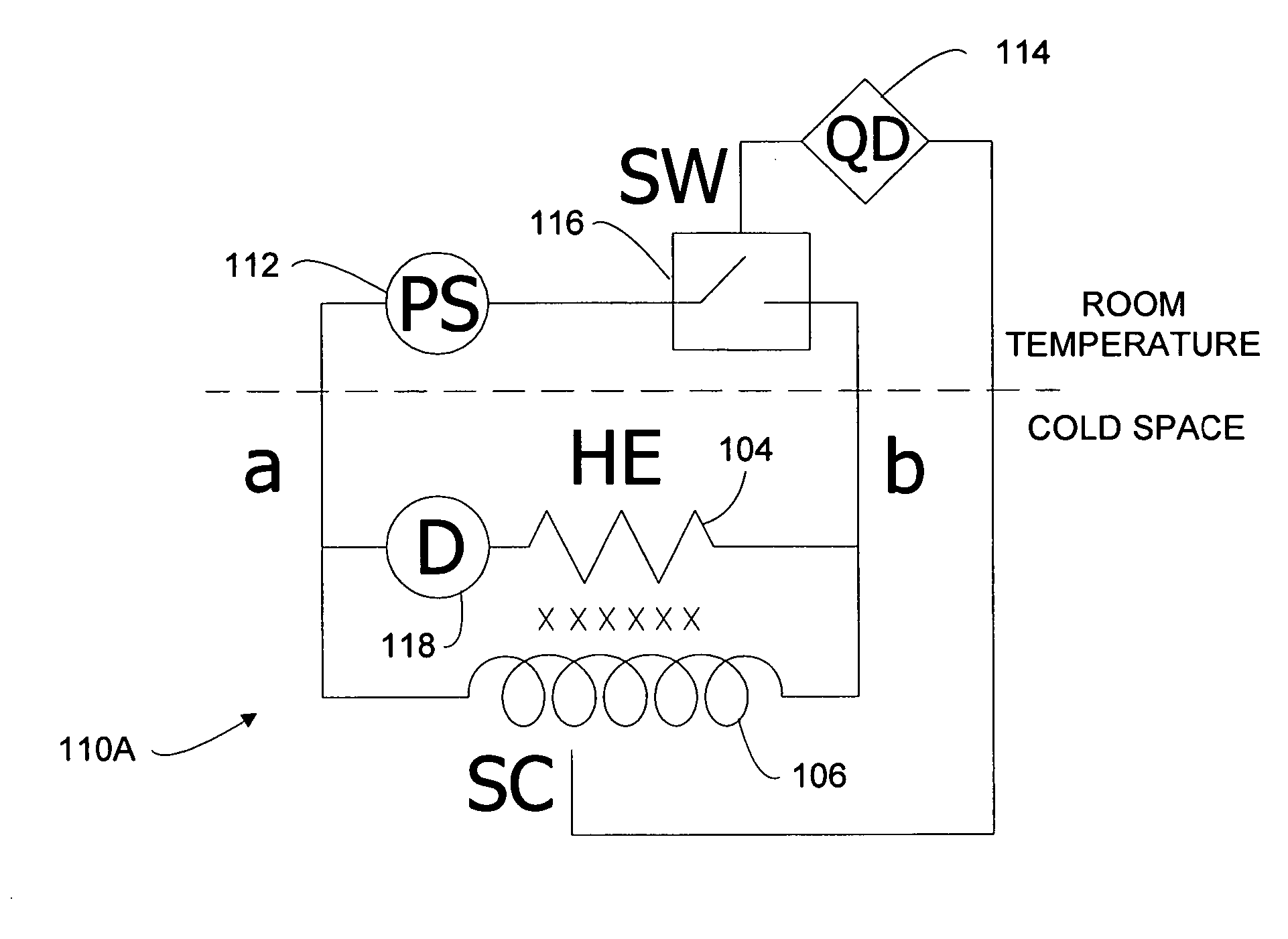
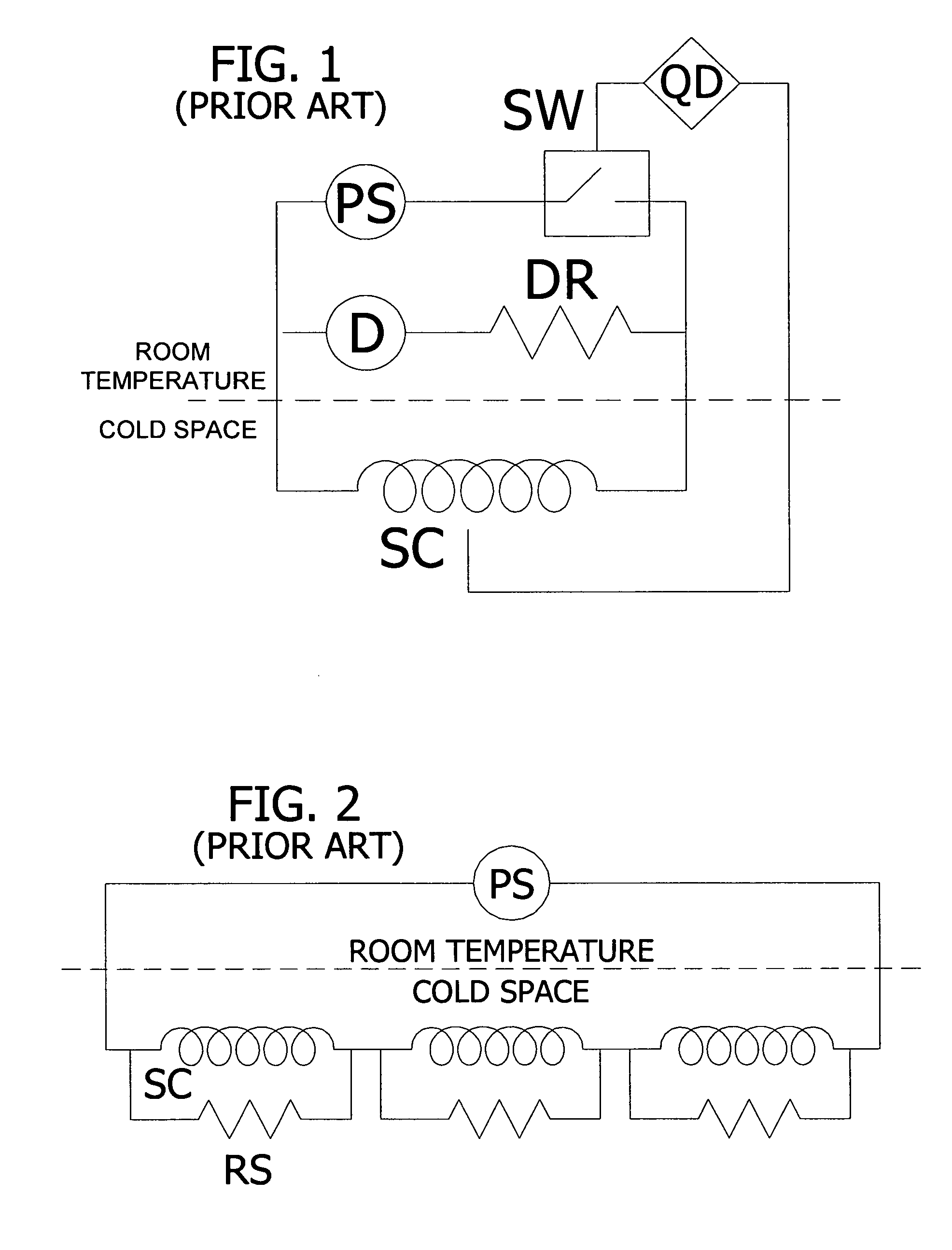
[0099] Coils containing HTS conductor are capable of operating at relatively high temperature, including a range of temperature for cryogenic nitrogen, 65 K to 77 K. The analysis is applied to a set of stand alone solenoid coils assumed to be wound from YBCO composite tape superconductor in a pancake configuration. The examples further demonstrate the heater design, and serve to provide a comparison between the inventive protection circuit 110 of FIGS. 12A and 12B, and the prior art external dump resistor circuit of FIG. 1.

[0100] The analysis is given for two solenoids defined by an inner winding radius a1, outer radius a2 and winding length 2b , as given in Table IV of APPENDIX B. The dimensions are such as to give a central field of 3.6 T for an average current density Jave over the winding pack of 100 A / mm2 and 150 A / mm2 in Case I and Case II, respectively. The magnetic stored energy per unit volume of the windings ev, is given in the table for the two coils, together with an av...


PUM


Abstract

A method of constructing a superconducting coil. The method includes embedding a plurality of heater elements throughout a superconducting coil. The heater elements are positioned according to a predetermined distribution and substantially in thermal contact with the coil for heating the coil in response to a quench condition. Other aspects of the invention involve an active protection circuit and a high temperature superconductor magnet that includes such an active protection circuit for internally dissipating stored magnetic energy in the event of a quench.

Description

BACKGROUND OF THE INVENTION [0001] The invention relates generally to superconducting magnets and, particularly, to quench protection of superconducting magnets. [0002] In general, superconductors are composite materials in the form of wires or flat tapes (e.g., round or rectangular). The composite conductor typically includes copper or silver for protection and stabilization in addition to a superconducting alloy or compound. The composite conductor may also have substantial fractions of other materials (e.g., bronze). Known high temperature superconductors (HTS) operating at typical temperatures of less than about 80 K include, among others, BSCCO, YBCO, and MgB2. Known low temperature superconductors (LTS) operating at typical temperatures of less than about 10 K include Nb3Sn and NbTi. A superconducting magnet often employs superconductors in a set of epoxy impregnated long solenoids. [0003] Because superconducting magnets are often designed to produce high magnetic fields, they...

Claims


Application Information

Patent Timeline
Patent Type & Authority Applications(United States)
IPC IPC(8): H02H7/00
CPCH01F6/02Y02E40/68H02H7/001H01F27/22Y02E40/60
Inventor MARKIEWICZ, W. DENIS
Owner FLORIDA STATE UNIV RES FOUND INC
Why Eureka
Try Eureka