Distribution optical elements and compound collecting lenses for broadcast optical interconnect

a technology of optical elements and broadcast optical interconnects, applied in the field of free space optical interconnects, can solve the problems of inability to achieve the effect of increasing the difficulty of driving electronics, and reducing the cost of optical components

Active Publication Date: 2008-01-10
LIGHTFLEET CORP
View PDF24 Cites 117 Cited by
  • Summary
  • Abstract
  • Description
  • Claims
  • Application Information

AI Technical Summary

Problems solved by technology

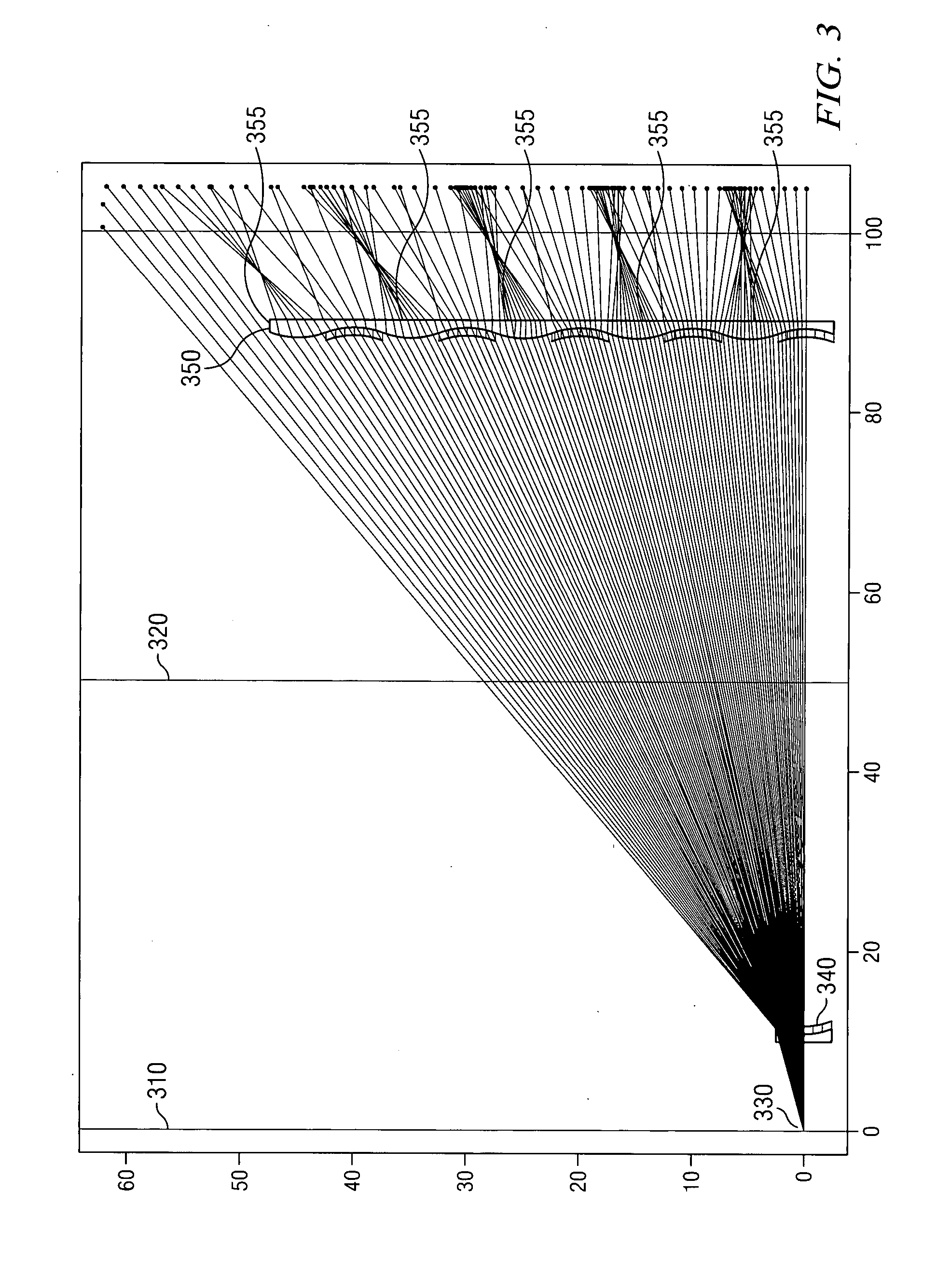
The problems of distortion of the focal plane with attendant global spherical aberration and unacceptable coma for those images of emitters far from the system axis are not addressed by this system unless a complex collector configuration of multiple-element lenses are used, much as is done in the design of flat-field, wide-angle lenses.
This solution typically requires a 5-to-7 element collecting lens and becomes prohibitively expensive in a system containing many modules.
As emitter power increases, the driving electronics becomes more difficult to implement and the power dissipation of the system increases.
These oblique beams produce highly distorted images on the focal plane.
However, the aspect of the distorted images becomes large for distant facets.
This distortion reduces the optical power falling on the target receiver and reduces the effective diameter of the focal region, leading to increased susceptibility to both static and dynamic misalignments of the components.
Additionally, an image that is highly distorted may partially illuminate a neighboring receiver, increasing the possibility of cross talk in the system.
The resulting image might be so large that the receiver grid interferes with the emitter grid.
Among these problems are focal plane distortion, image-region distortion at individual receivers, inadequate intensity, especially when scaling to larger systems.

Method used


Image

  • Distribution optical elements and compound collecting lenses for broadcast optical interconnect
  • Distribution optical elements and compound collecting lenses for broadcast optical interconnect
  • Distribution optical elements and compound collecting lenses for broadcast optical interconnect

Examples


Embodiment Construction

[0076] The invention and the various features and advantageous details thereof are explained more fully with reference to the nonlimiting embodiments that are illustrated in the accompanying drawings and detailed in the following description. Descriptions of well known starting materials, processing techniques, components and equipment are omitted so as not to unnecessarily obscure the invention in detail. It should be understood, however, that the detailed description and the specific examples, while indicating preferred embodiments of the invention, are given by way of illustration only and not by way of limitation. Various substitutions, modifications, additions and / or rearrangements within the spirit and / or scope of the underlying inventive concept will become apparent to those skilled in the art from this disclosure.

[0077] The below-referenced U.S. patents disclose embodiments that are useful for the purposes for which they are intended. The entire contents of U.S. Pat. Nos. 6...


PUM


Abstract

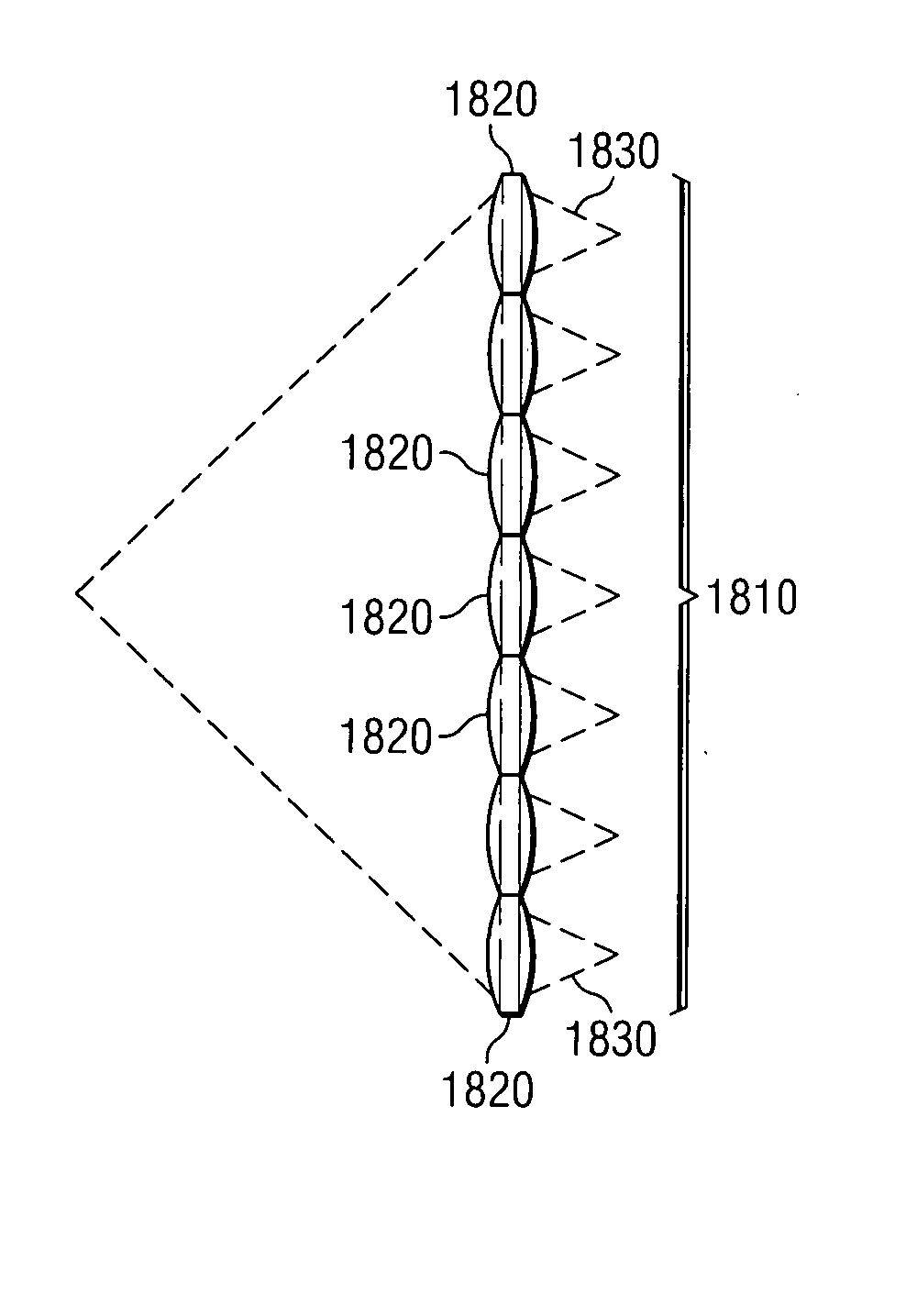
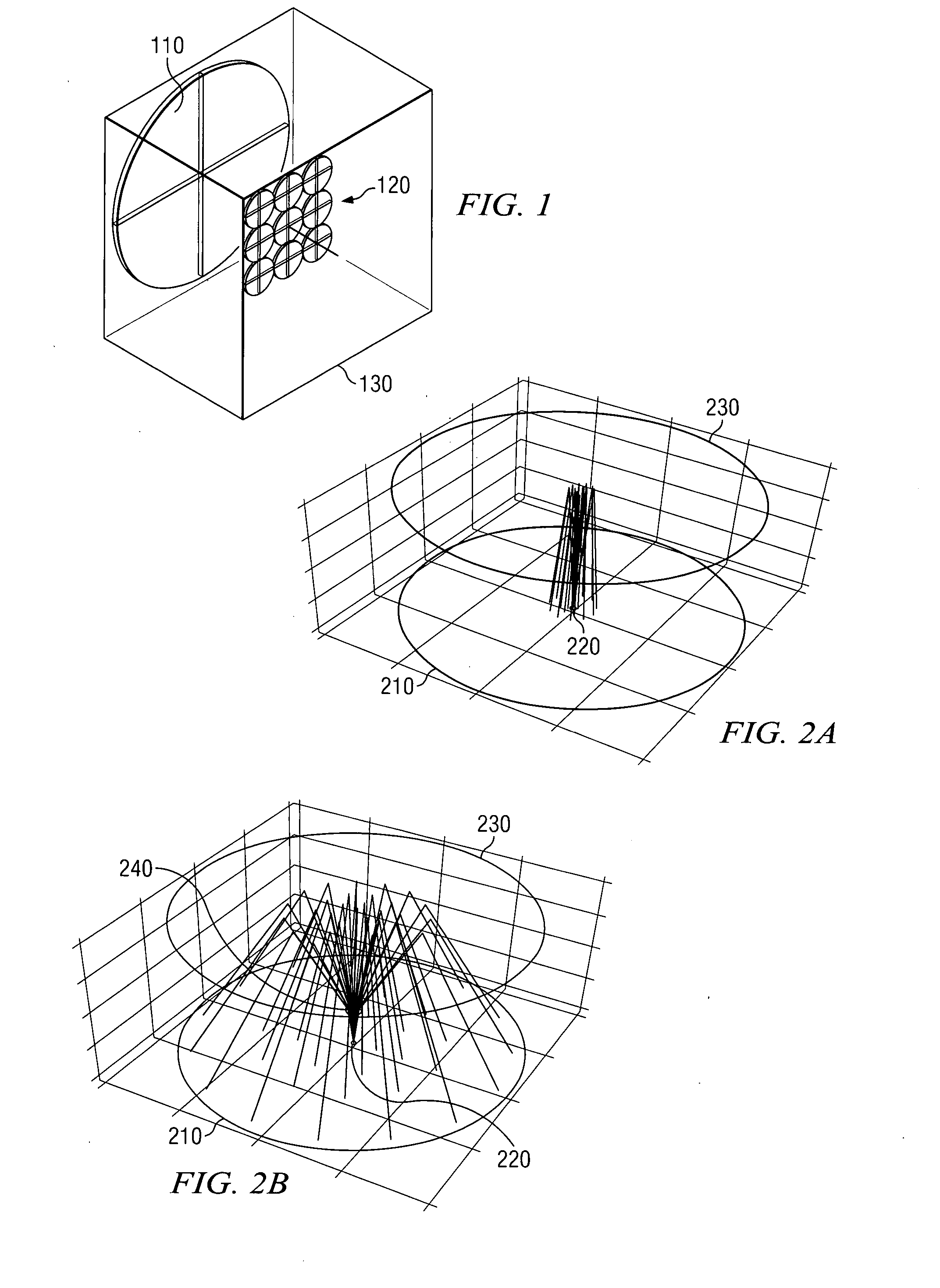
Methods and apparatus are described for distribution optical elements and compound collector lenses for a broadcast interconnect. An apparatus includes a broadcast optical interconnect including: a plurality of nodes positioned to define a node array, each of the plurality of nodes having at least one optical signal emitter and a plurality of optical signal receivers positioned to define a receiver array that substantially corresponds to the node array; and a plurality of optics optically coupled to the array of nodes, the plurality of optics positioned to define an optics array that substantially corresponds to the node array and the receiver array, each of the plurality of optics including at least one optical distributing element and an optical collecting element, wherein an optical signal from the optical signal emitter is fanned-out by the at least one optical distributing element of one of the optics and broadcast to one of the plurality of receivers of all of the plurality of nodes by the optical collecting element of all of the plurality of optics.

Description

CROSS-REFERENCES TO RELATED APPLICATIONS [0001] This application claims a benefit of priority under 35 U.S.C. 119(e) from provisional patent application U.S. Ser. No. 60 / 813,970, filed Jun. 14, 2006 and is also a continuation-in-part of, and claims a benefit of priority under 35 U.S.C. 120 from copending utility patent application U.S. Ser. No. 11 / 796,133 filed Apr. 25, 2007, which in-turn is a continuation-in-part of, and claims a benefit of priority under 35 U.S.C. 120 from copending utility patent application U.S. Ser. No. 10 / 702,227 filed Nov. 5, 2003, which in-turn claims a benefit of priority under 35 U.S.C. 119(e) from both provisional patent application U.S. Ser. No. 60 / 423,939, filed Nov. 5, 2002 and provisional patent application U.S. Ser. No. 60 / 432,141, filed Dec. 10, 2002, the entire contents of all of which are hereby expressly incorporated herein by reference for all purposes.BACKGROUND OF THE INVENTION [0002] 1. Field of the Invention [0003] The invention relates gen...

Claims


Application Information

Patent Timeline
Patent Type & Authority Applications(United States)
IPC IPC(8): H04J14/00H04B10/00
CPCH04B10/803
Inventor DRESS, WILLIAM BENJAMINMAGEE, FREDERICK NORMAN
Owner LIGHTFLEET CORP
Why Eureka
Try Eureka