
Prosthetic Knee

a technology for prosthetic joints and knees, applied in the field of prosthetic knees, can solve the problems of not being able to adequately simulate femoral roll back, unable to permit posterior/anterior translation of femoral bearing surfaces with respect, and unable to permit anterior/anterior translation of femoral bearing surfaces

Inactive Publication Date: 2008-01-10
RICHARDSON RODNEY LAN WALTER
View PDF10 Cites 140 Cited by
  • Summary
  • Abstract
  • Description
  • Claims
  • Application Information

AI Technical Summary

Problems solved by technology

However, unlike the anatomical joint, stabilised knee joints of this type permit little, if any, anterior-posterior translation, lateral angulation, or rotation.
However, prosthetic joints of this type may not adequately simulate femoral roll back.
For example, they may not permit posterior / anterior translation of the femoral bearing surface with respect to the tibial bearing surface during flexion / extension.
Further, known condylar surface prostheses may not permit rotation of the femoral bearing surface with respect to the tibial bearing surface during flexion / extension.
The bearing surfaces used in any such hard on soft articulation may create wear debris which is a major cause of osteolysis and implant failure.
Lack of lubrication on the articulating surfaces of a prosthetic joint may also lead to joint failure.
Younger patients sometimes delay having surgery due to the short lifespan of artificial joints.
While it may by possible to overcome these difficulties by using harder wearing biomaterials, the design of artificial knee joints may not necessarily facilitate use of such materials.

Method used


Image

  • Prosthetic Knee
  • Prosthetic Knee
  • Prosthetic Knee

Examples


Embodiment Construction

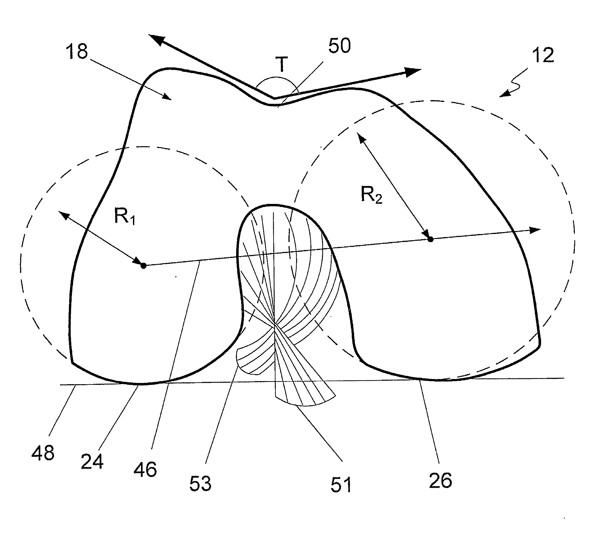
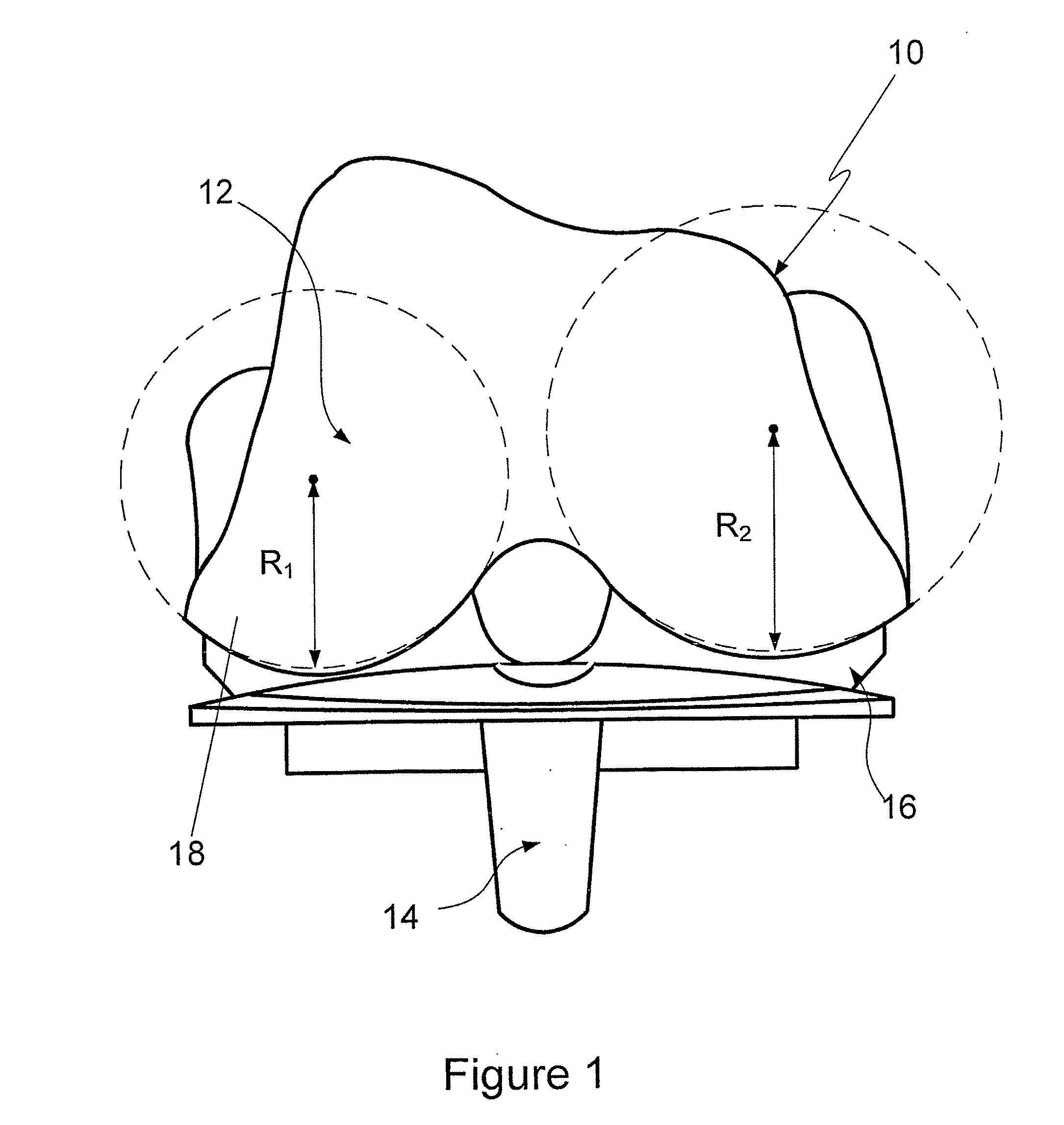
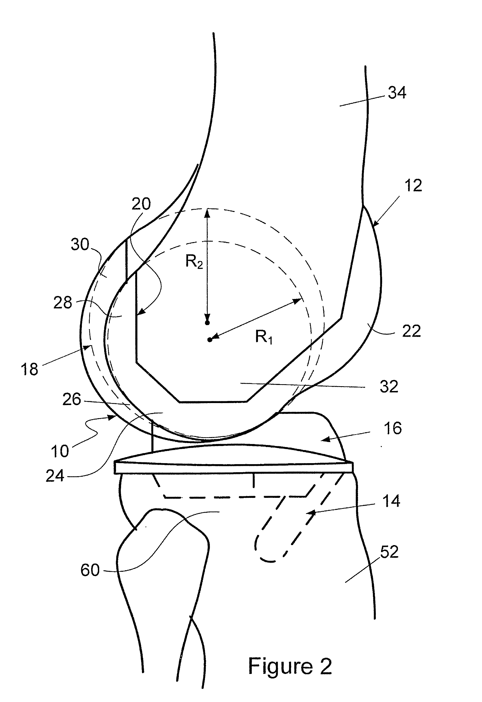
[0057] As used herein, the following directional definitions apply. Anterior and posterior mean nearer the front and near the back of the body respectively. Thus, for the knee joint described herein, anterior refers to that portion of the knee that is nearer the front of the body when the leg is in an extended position. Proximal and distal respectively mean nearer to and further away from the root of the structure in question. For example, the distal end of the femur is the end of the femur that forms part of the knee joint and the proximal end of the femur is the end of the femur that forms part of the hip joint. Medial and lateral mean nearer to and further away from the sagittal plane respectively. The sagittal plane is the imaginary vertical plane that divides the body into left and right halves.

[0058] The prosthetic knee 10 shown in FIG. 1 advantageously restores normal functionality to the knee of a person. The prosthetic knee 10 utilises the tendons and ligaments surrounding...


PUM


Abstract

A prosthetic knee for replacing the knee of a patient including: (a) a femoral component being coupable to a resected distal end of a femur of patient; (b) a tibial component being couplable to a resected proximal end of a tibia of the patient; and (c) an insert, wherein the femoral component and the tibial component articulate by way of the insert arrangable therebetween, and a curved articular surface of the insert is adapted to pivot with respect to a corresponding curved articular surface of the tibial component.

Description

TECHNICAL FIELD OF THE INVENTION [0001] The present invention relates to a prosthetic knee. BACKGROUND OF THE INVENTION [0002] Disease or trauma that affect the articular surfaces of a knee can be treated by surgically replacing the ends of bones with prosthetic femoral and tibial implants. The femoral and tibial implants typically articulate by way of an insert arranged therebetween. The process of replacing the ends of bones in this manner is known as a total knee replacement. [0003] Knee joint prostheses can be classified into two basic types. The first type, referred to as “stabilised” prosthesis, has hinge or ball type joints used as substitutes for the anatomical knee joint. In this type of knee joint, the movement of the joint is constrained by a hinge pin or ball and socket. The stabilised knee joint is useful where little reliance can be placed on the surrounding tendons and ligaments to stabilise the joint. However, unlike the anatomical joint, stabilised knee joints of th...

Claims


Application Information

Patent Timeline
IPC IPC(8): A61F2/38
CPCA61F2/3868A61F2002/30131A61F2002/30879A61F2230/0013A61F2002/30327A61F2310/00023A61F2310/00029A61F2310/00179A61F2310/00017A61F2/38
Inventor RICHARDSON, RODNEY LAN WALTER
Owner RICHARDSON RODNEY LAN WALTER
Learn More