
Electronic Signature Security System

Active Publication Date: 2008-01-10
TOPAZ SYST
View PDF71 Cites 76 Cited by
  • Summary
  • Abstract
  • Description
  • Claims
  • Application Information

AI Technical Summary

Benefits of technology

[0009] One embodiment of the invention provides a system, method, and device to enhance the security and compliance of electronic signatures with existing regulations and good practice. In one implementation, an electronic signature is captured on a peripheral device that is not contained in the main processor and may be located remotely from the processor by a few feet or thousands of miles. The system binds signature and record data together at the point-of-use to reduce the likelihood that someone may be able to hack into the transmission medium, encrypted or not, and obtain the raw signature data. By binding or associating the signature and record data together at the point-of-use, each record has a unique key, further foiling attempts at hacking. Through the use of a shared secret that is not transmitted, or never transmitted over the transmission medium, but which is related to a programmed value such as a serial number or a serial number that is modified by a real-time computed (RTC) value, or which can be reset by a command without exchanging data, security is further enhanced.
[0014] One aspect of the invention provides for capturing a digital signature and / or biometric signature on a point-by-point (or segment-by-segment) basis and separately encrypting said points to the record data. The separately encrypted signature sample points or segments may be stored separately, at transmitting and / or receiving devices, so that the complete signature does not appear on the same processor or memory at any one time. This prevents rogue programs from capturing or determining the signature by snooping on a processor or memory.

Problems solved by technology
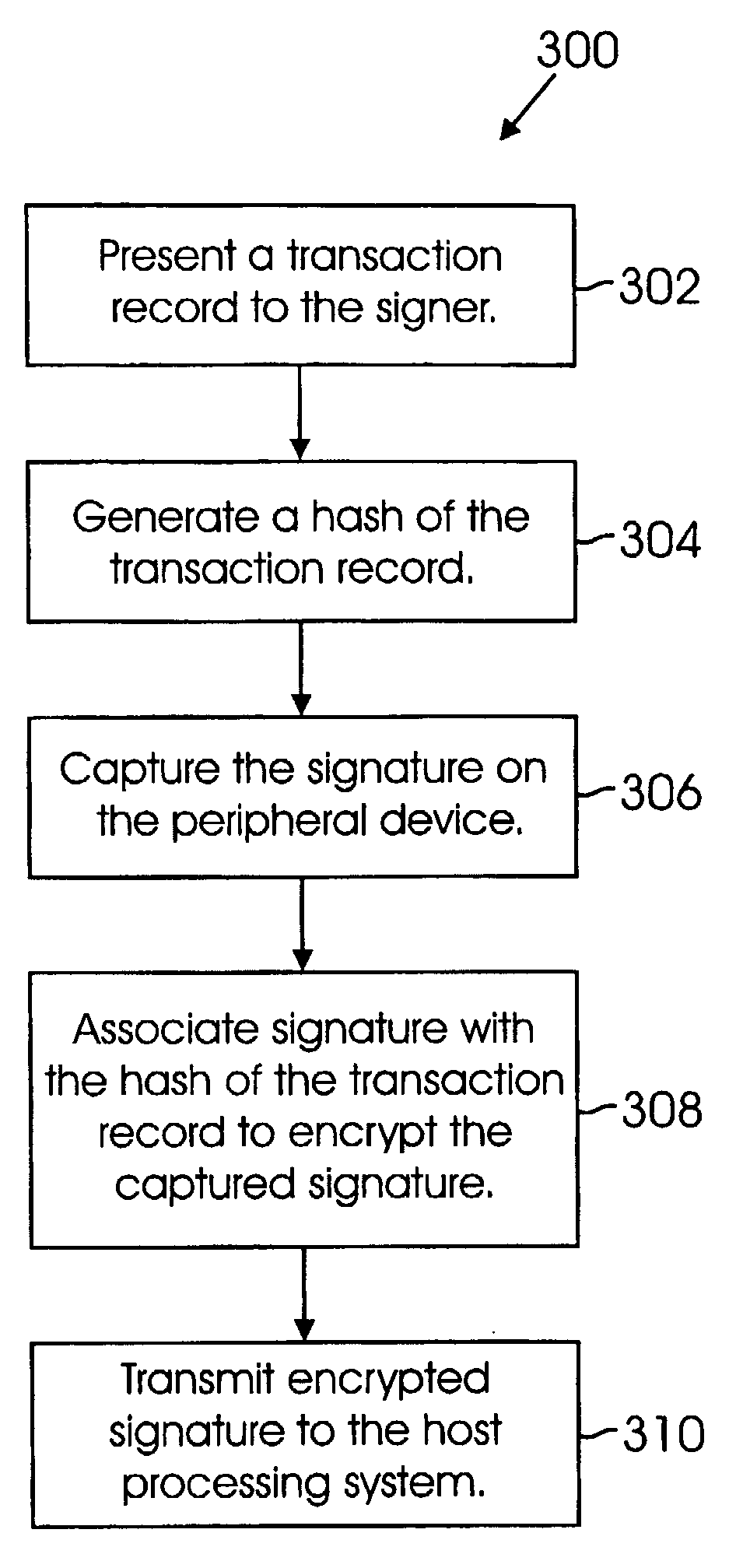
There are several weaknesses with this approach.
First, the transaction record used to encrypt the signature is displayed with the transaction data, thereby making it susceptible to unauthorized access.

Method used


Image

  • Electronic Signature Security System
  • Electronic Signature Security System
  • Electronic Signature Security System

Examples


Embodiment Construction

[0040] In the following description numerous specific details are set forth in order to provide a thorough understanding of the invention. However, one skilled in the art would recognize that the invention might be practiced without these specific details. In other instances, well known methods, procedures, and / or components have not been described in detail so as not to unnecessarily obscure aspects of the invention.

[0041] In the following description, certain terminology is used to describe certain features of one or more embodiments of the invention. For instance, the term “electronic” means relating to technology having electrical, digital, magnetic, wireless, optical, electromagnetic, or similar capabilities. The term “electronic record” means a contract or other record created, generated, sent, communicated, received, or stored by electronic means. The term “electronic signature” means an electronic sound, symbol, process, or other information, attached to or logically associ...


PUM


Abstract

One embodiment of the invention enhances the security of electronic signatures during transmission. A peripheral device, which may be located remotely and separate from a host processing system, captures the signature. The peripheral device then binds the signature to the particular transaction record and transmits it to the host processing system. The host processing system validates or confirms the received signature before accepting the transaction. Binding the signature and record data together at the point-of-use reduces the likelihood that someone may be able to hack into the transmission medium, encrypted or not, and obtain the raw signature data. By binding or associating the signature and transaction record data together at the point-of-use, each transaction has a unique key, further foiling attempts at hacking. In various implementations, rather than associating the whole signature with the transaction record data, signature sample points or segments are encrypted with transaction record data.

Description

CLAIM OF PRIORITY [0001] The present patent application claims priority on and is a Continuation-in-Part of U.S. patent application Ser. No. 11 / 027,525, titled “Electronic Signature Capture Security System,” filed Dec. 30, 2004, currently pending and assigned to the assignee hereof, and hereby expressly incorporated by reference.FIELD [0002] Various embodiments of the invention pertain to securing electronic signatures. At least one embodiment of the invention pertains to a system and method for capturing and securing electronic signatures by a hashing algorithm. BACKGROUND [0003] In recent years, an increasing number of transactions are being conducted over electronic mediums. Law, regulations, and industry standards have been adopted to facilitate the use of electronic records and signatures in interstate and foreign commerce. Some of these laws and regulations specify that an acceptable technology for electronic signatures must be linked to data in such a manner that if the data ...

Claims


Application Information

Patent Timeline
IPC IPC(8): H04L9/00
CPCG06F21/64G06Q30/06G06Q20/401G06Q20/382H04L63/123H04L9/3247H04L2209/56H04L9/3236H04L9/32H04L9/3297H04L9/3263H04L63/126
Inventor ZANK, ANTHONY
Owner TOPAZ SYST
Learn More