Power Driving Assembly for a Disc Brake Being Resurfaced

a technology of power driving assembly and disc brake, which is applied in the direction of turning apparatus, manufacturing tools, portable lathes, etc., can solve the problems of disc brake wear, needing to be resurfaced, time-consuming and difficult to carry out, etc., and achieve the effect of effectively coupling the gear and the disc brak

Inactive Publication Date: 2008-01-17
SCANGRIP
View PDF9 Cites 0 Cited by
  • Summary
  • Abstract
  • Description
  • Claims
  • Application Information

AI Technical Summary

Benefits of technology

[0034] A carrier can according to the invention be connected to the automotive wheel hub assembly for reliably and effectively coupling the gear with the disc brake.
[0035] The carrier is, in an advantageously embod...

Problems solved by technology

The disc brakes of a vehicle are subject to wearing when driving the vehicle.
When the disc brakes are worn-out, they need to be resurfaced.
This process was, however, time-consuming and difficult to carry out.
The portable disc brake lathe known from the above mentioned U.S. Pat. No. 4,854,199 has however a complicated and costly construction and is moreover difficult to mount upon the caliper mounting brackets.
The above-described arrangement of the power driving assembly known from the U.S. Pat. No. 5,549,023 implies however the serious problem that it is a very time-consuming and also difficult to adjust the power driving assembly and the disc brake to be resurfaced into such mutual operation positions that the resurfacing of the disc brake can be carried out effectively and...

Method used


Image

  • Power Driving Assembly for a Disc Brake Being Resurfaced
  • Power Driving Assembly for a Disc Brake Being Resurfaced
  • Power Driving Assembly for a Disc Brake Being Resurfaced

Examples


Embodiment Construction

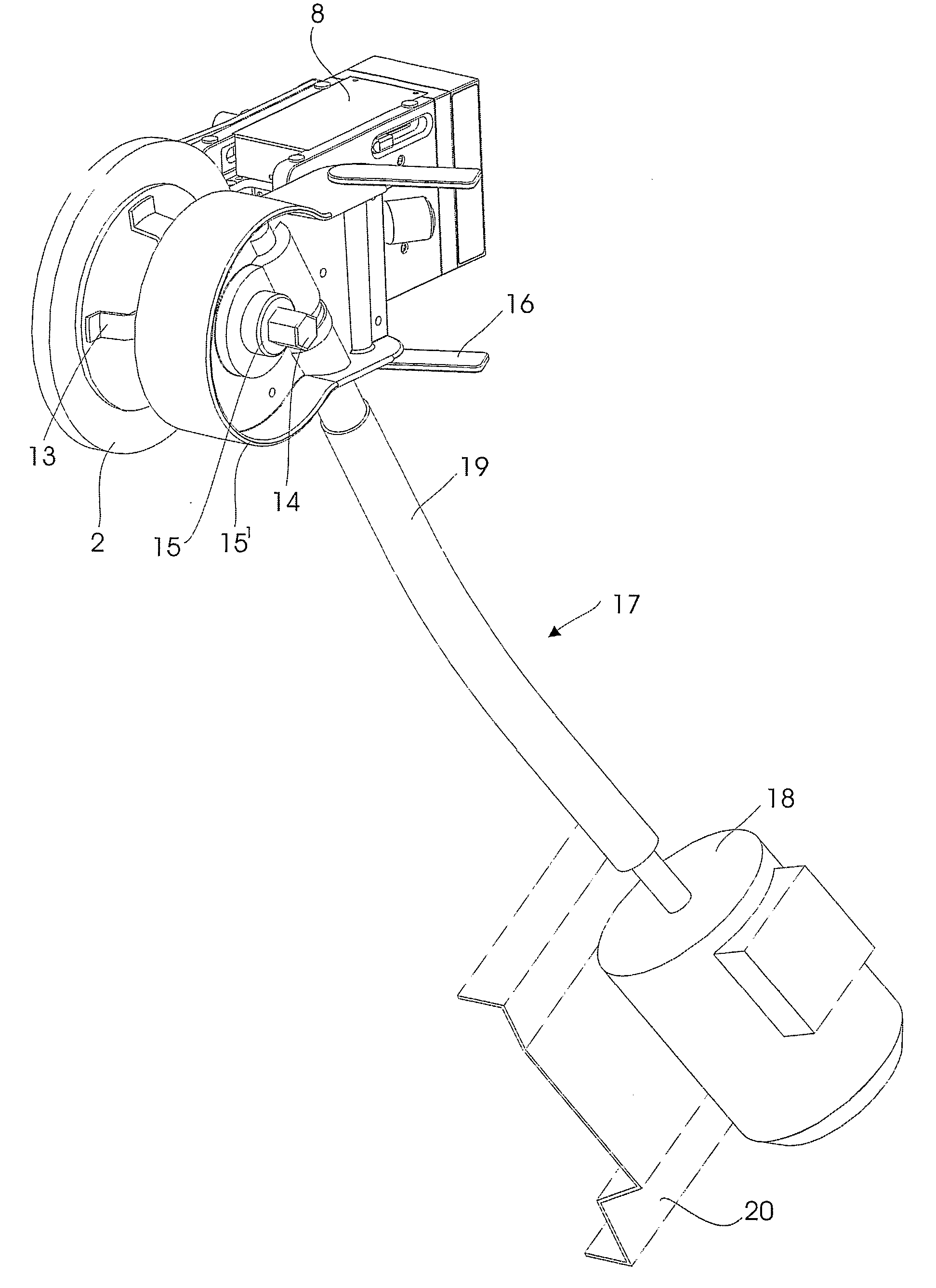
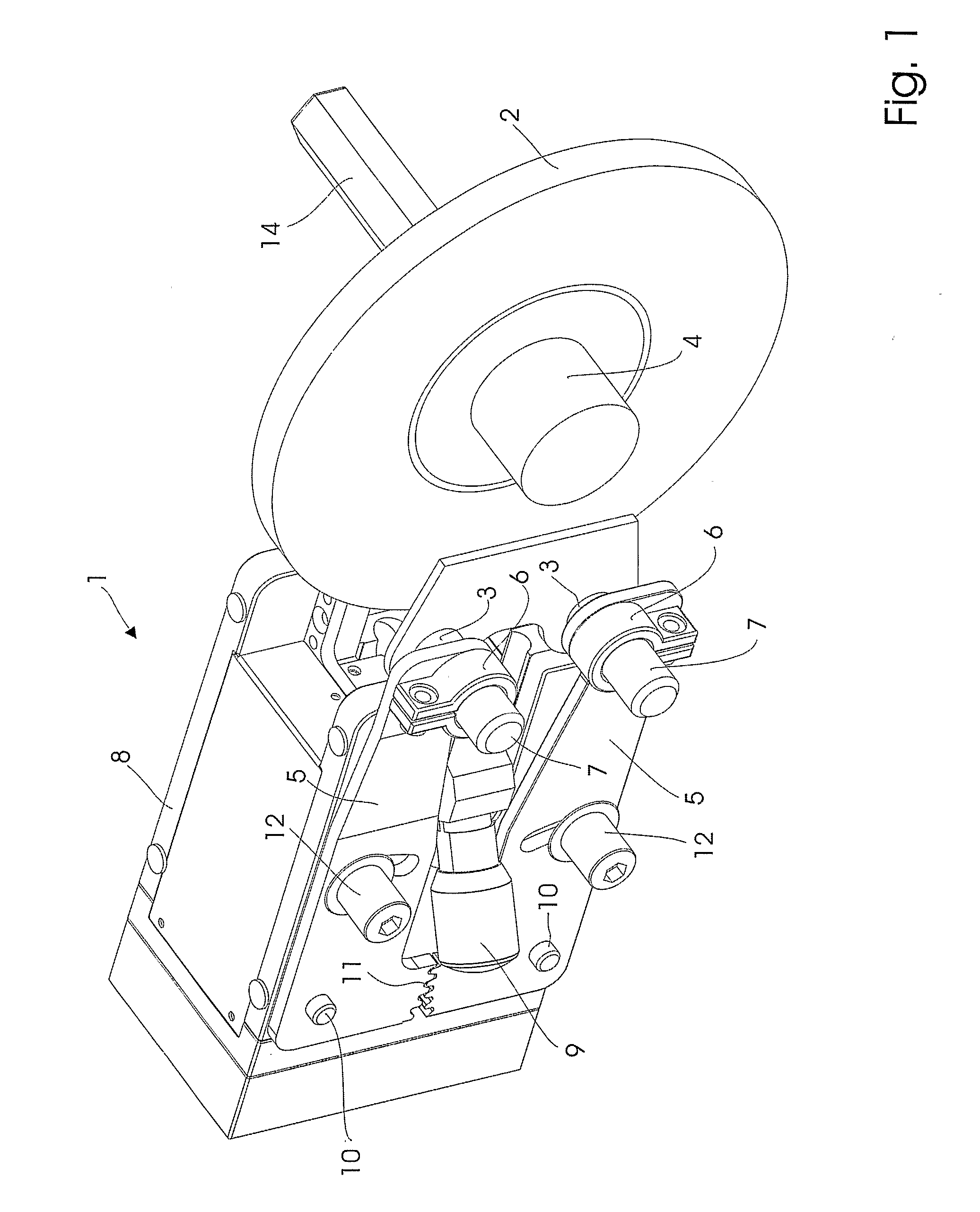
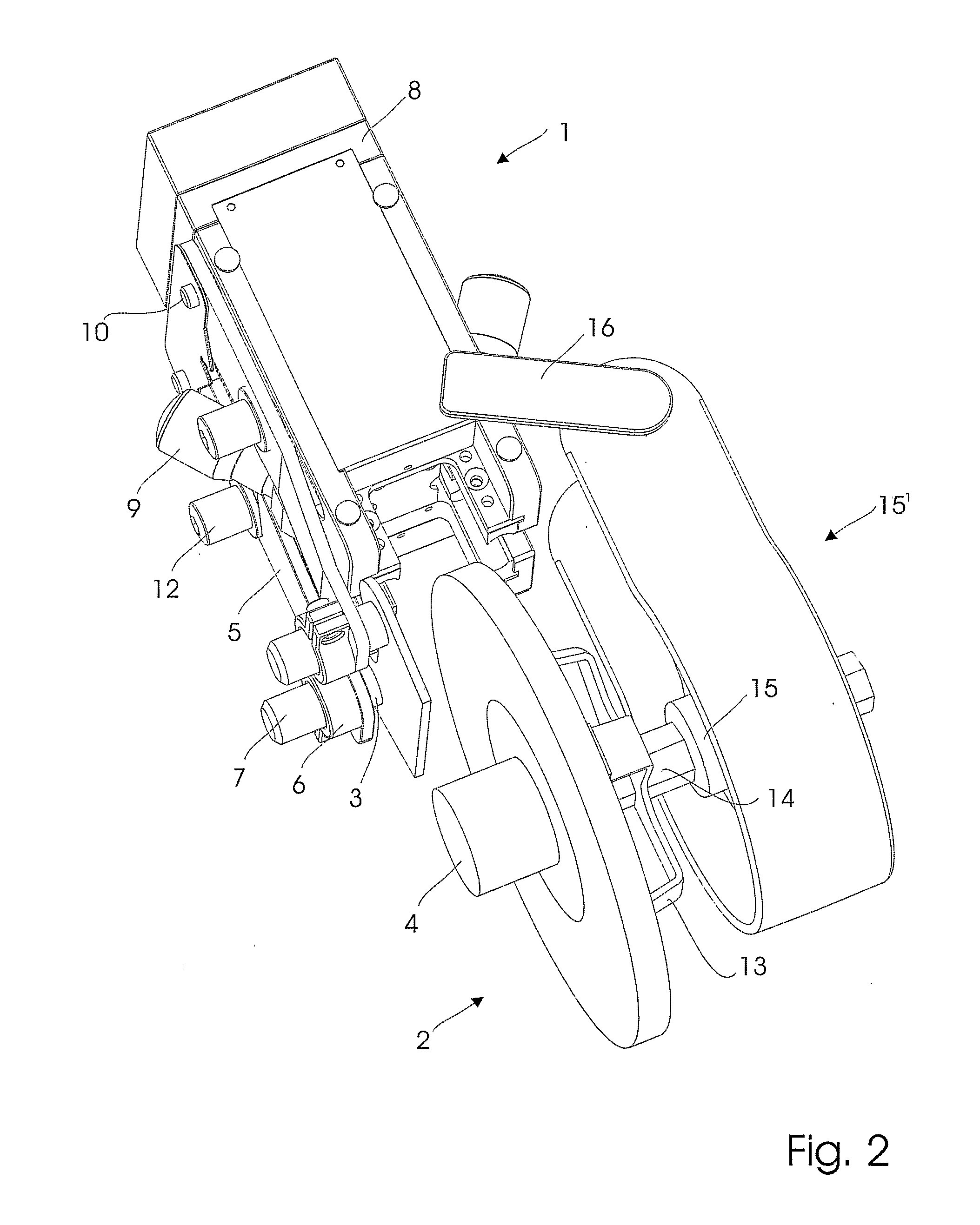
[0047] A schematically shown disc brake lathe 1 is, after removing the wheel and the caliper of a vehicle (not shown), in FIG. 1 in position for resurfacing a disc brake 2.

[0048] The disc brake lathe 1 is mounted onto the caliper mounting brackets 3 of the wheel hub assembly 4 of the vehicle by means of adapter arms 5 having, in this case, split bushings 6 placed on adapters 7 mounted into the holes in the caliper mounting brackets for mounting the now removed caliper.

[0049] The resurfacing of the disc brake takes place by means of cutting tips (not shown) on a slide in the disc brake lathe head 8. The cutting depth is set by means of micrometers 9.

[0050] The distance between the adapter holes in the caliper mounting brackets can be varied in dependence of the make of vehicle. The adapter arms are therefore pivotally mounted on pivots 10 on the disc brake lathe head whereby the distance between the split bushings of the adapter arms easily can be adjusted to the distance between ...


PUM

PropertyMeasurementUnit
Lengthaaaaaaaaaa
Poweraaaaaaaaaa
Flexibilityaaaaaaaaaa

Abstract

A power driving assembly (17) serves for rotating a disc brake (2) being resurfaced by means of a disc brake lathe (1) mounted onto the caliper mounting brackets (3) of a vehicle wheel hub assembly (4). The power driving assembly (17) comprises a motor (18) and a shaft (19) for transmitting the power from the motor (18) to the disc brake (2). The shaft is a flexible shaft (19), which is connected to a gear (15) of a gearbox (15′), which again is connected to the disc brake (2). The motor (18) and the disc brake (2) can be correctly connected to each other quickly and easily.

Description

FIELD OF THE INVENTION [0001] The invention relates to a power driving assembly for rotating a disc brake being resurfaced by means of a disc brake lathe mounted onto e.g. the caliper mounting brackets of a vehicle wheel hub assembly, and also to a method for using said power driving assembly. [0002] The power driving assembly comprises more specifically a motor and a shaft for transmitting the power from the motor to the disc brake. BACKGROUND ART [0003] The disc brakes of a vehicle are subject to wearing when driving the vehicle. When the disc brakes are worn-out, they need to be resurfaced. [0004] To perform this process the disc brakes originally were removed from the vehicle and resurfaced by means of an independent brake lathe. This process was, however, time-consuming and difficult to carry out. [0005] In order to remedy said drawbacks of the earlier technique portable disc brake lathes were developed for resurfacing a disc brake without removing this from the vehicle. [0006]...

Claims


Application Information

Patent Timeline
IPC IPC(8): B23B5/04
CPCB23B5/04Y10T82/21B23B2260/068
Inventor BORRING, ANDERS
Owner SCANGRIP
Why Eureka
Try Eureka