
Embroidery Sewing Machine With Printing Function

a sewing machine and printing function technology, applied in embroidering machines, automatic machines, textiles and paper, etc., can solve the problems of reducing the printing area, the printing machine employing the above construction provides poor printing quality, and no consideration nor ideas were devised to address such problems in the above conventional embroidery

Inactive Publication Date: 2008-01-17
BROTHER KOGYO KK
View PDF2 Cites 8 Cited by
  • Summary
  • Abstract
  • Description
  • Claims
  • Application Information

AI Technical Summary

Benefits of technology

[0011]As described above, sufficient printable area can be secured within the cloth holding frame according to the embroidery sewing machine with printing function of the present invention.

Problems solved by technology

Thus, the printer employing the above construction provides poor printing quality in the acceleration / deceleration area corresponding to the acceleration / deceleration state.
However, such restriction in the acceleration / deceleration area of the stepping motor gives rise to a problem of reduced printable area.
However, no considerations were given nor ideas were devised to address such problems in the above conventional embroidery sewing machine.
Especially in the case of household embroidery sewing machines, there was a limitation in the spacing between the sewing needle and the foot, in other words, the distance in the direction parallel to the lengthwise direction of the bed, which reduces the printable area to a considerable extent.

Method used


Image

  • Embroidery Sewing Machine With Printing Function
  • Embroidery Sewing Machine With Printing Function
  • Embroidery Sewing Machine With Printing Function

Examples


Embodiment Construction

[0024]One embodiment of the present invention will be described in detail with reference to the drawings for the purpose of describing the present invention.

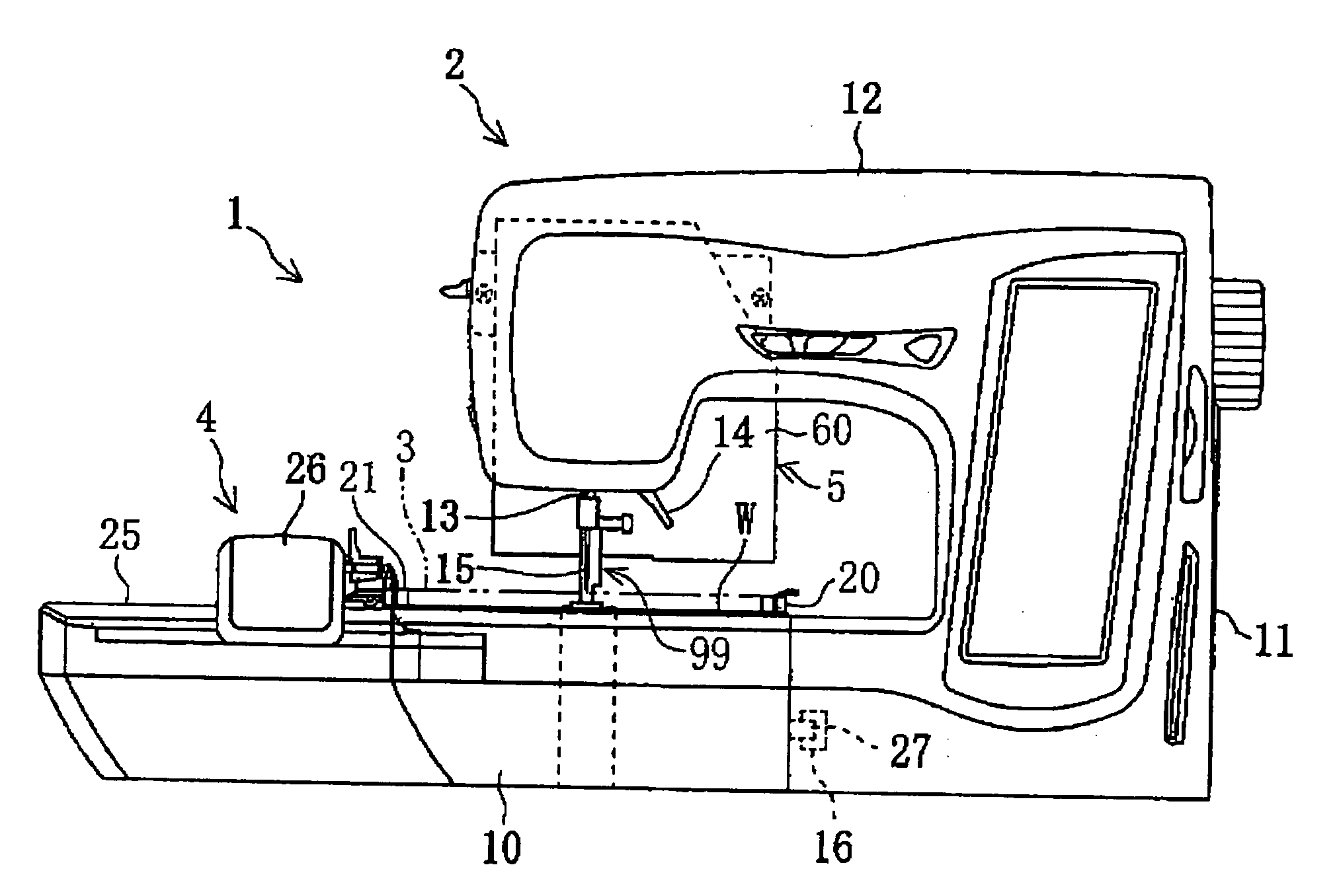
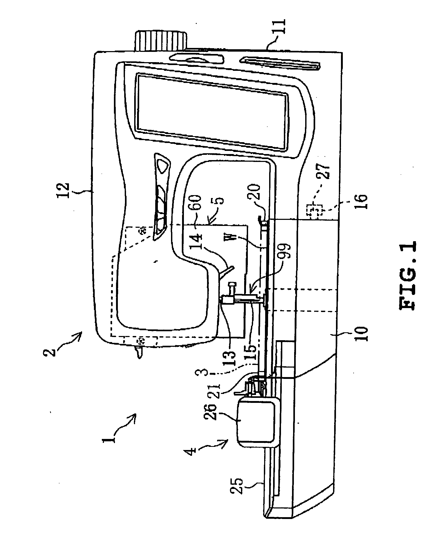
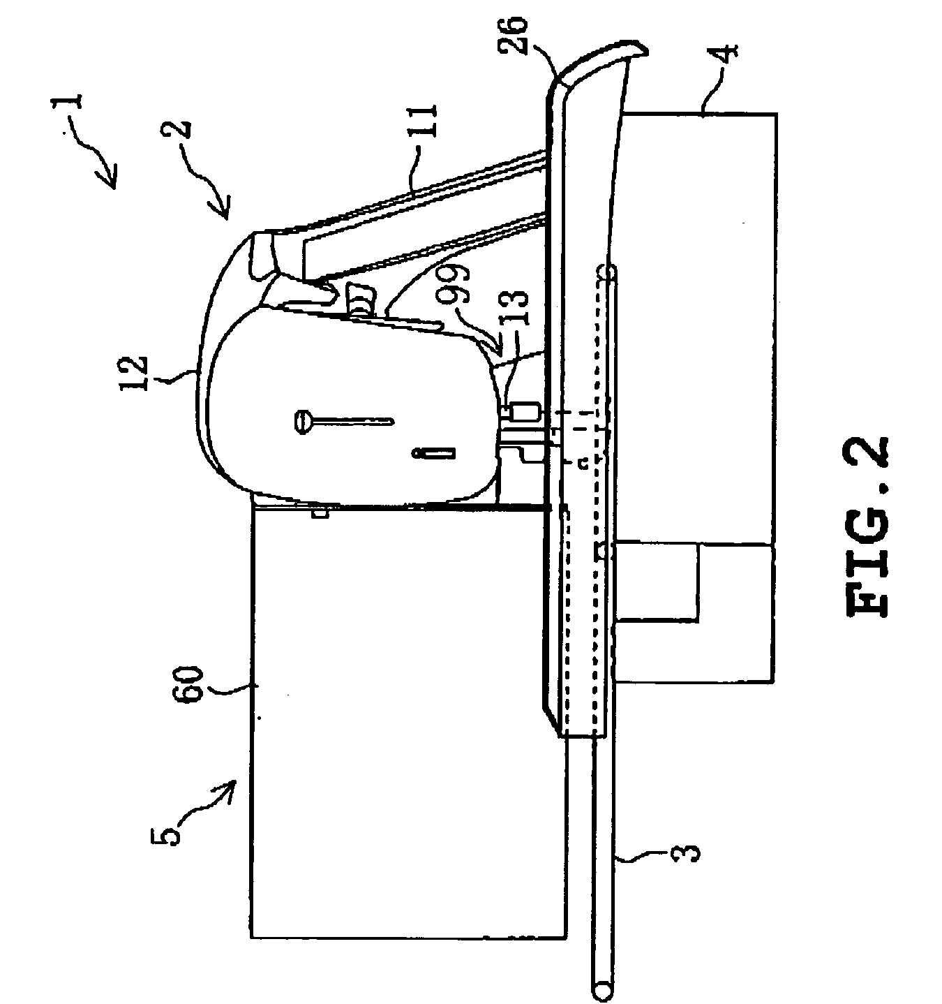
[0025]Referring to FIGS. 1 to 3, an embroidery sewing machine with printing function 1 in accordance with tho present embodiment has a sewing machine body 2 capable of sewing a workpiece cloth W (refer to FIG. 8). The sewing machine body 2 has a frame drive unit 4 mounted thereto and the frame drive unit 4 has a detachable rectangular cloth holding frame 3 holding the workpiece cloth attached thereto. As will be described in detail later, the frame drive unit 4, as shown in FIG. 3, is adapted to move the cloth holding frame 3 and consequently the workpiece cloth W independently in an X-direction (lateral direction) which is a first direction parallel to the lengthwise direction of a bed 10 and a Y-direction (longitudinal direction) which is the second direction perpendicular thereto. As will be described later also, the sewing m...


PUM


Abstract

An embroidery sewing machine with printing function (1) including a sewing machine body (2) having a bed (10), a foot (11), an arm (12), and capable of sewing a workpiece cloth (W) by a sewing unit (99); a cloth holding frame (3) holding the workpiece cloth (W) to be sewn; a frame drive unit (4) moving the cloth holding frame 3 independently in two mutually perpendicular directions in a horizontal plane; an ink-jet printer (5) having a print head (61) printing the workpiece cloth (W) held by the cloth holding frame (3); the embroidery sewing machine with printing function (1) characterized in that the frame drive unit (4) includes a first drive mechanism (45) that moves the cloth holding frame (3) in a first direction parallel with a lengthwise direction of the bed (10); and a second drive mechanism (30) that moves the cloth holding frame (3) in a second direction perpendicular to the first direction and the print head (61) of the printer (5) includes nozzle arrays (61c to 61f) aligning a plurality of ink-jet nozzles (61b) parallel in the first direction and the printer (5) prints the workpiece cloth (W) while moving the cloth holding frame (3) in the second direction by the second drive mechanism (30), thereby to increase a printable area K.

Description

TECHNICAL FIELD[0001]The present invention relates to an embroidery sewing machine with printing function capable of printing a workpiece cloth by an ink-jet printing unit.BACKGROUND TECHNOLOGY[0002]A conventional embroidery sewing machine includes a sewing machine body; a cloth holding frame that holds a workpiece cloth in a stretched manner; a frame drive unit that drives the cloth holding frame independently in two mutually perpendicular directions in a horizontal plane. Provided in an arm of the sewing machine body is a needle bar vertically moving mechanism that vertically moves the needle bar. Also, various types of loop takers are provided in a bed of the sewing machine body. Household embroidery sewing machines having the frame drive unit installed in the bed of the sewing machine body have been reduced to practice in the household sewing machine field also.[0003]In recent years, embroidery sewing machines have been suggested that allow both embroidery and print images to be...

Claims


Application Information

Patent Timeline
IPC IPC(8): D05C7/00B41J2/01B41J2/165B41J2/18B41J3/28B41J3/407B41J29/00B41J29/02B41J29/38D05B21/00D05B39/00D05C7/02
CPCB41J3/28B41J3/4078D05C7/02B41J29/38D05B21/00B41J29/02D06B11/0073
Inventor KUKI, MASAKAZUKITAZAWA, HIROSHI
Owner BROTHER KOGYO KK
Learn More