Solar Cell Module Connector

a solar cell and module technology, applied in the direction of coupling device connection, radiation control device, pv power plant, etc., can solve the problem that the generated heat cannot be dissipated sufficiently, and achieve the effect of improving reliability and high productivity

Inactive Publication Date: 2008-01-17
SANSHA ELECTRIC MFG +1
View PDF0 Cites 46 Cited by
  • Summary
  • Abstract
  • Description
  • Claims
  • Application Information

AI Technical Summary

Benefits of technology

[0005] An object of the present invention is to provide thin solar cell module connectors, which have improved reliability, are enduring for long term use, and have high productivity. Means to Solve the Problem

Problems solved by technology

According to this technique, however, when a solar cell module with which a connector is connected in parallel is not generating electric power, current from other solar cell modules connected in series with that inoperative solar cell module flows through the diode of the connector connected in parallel with that inoperative solar cell module.
In such case, the diode generates heat, but the generated heat cannot be dissipated sufficiently.

Method used


Image

  • Solar Cell Module Connector
  • Solar Cell Module Connector
  • Solar Cell Module Connector

Examples


first embodiment

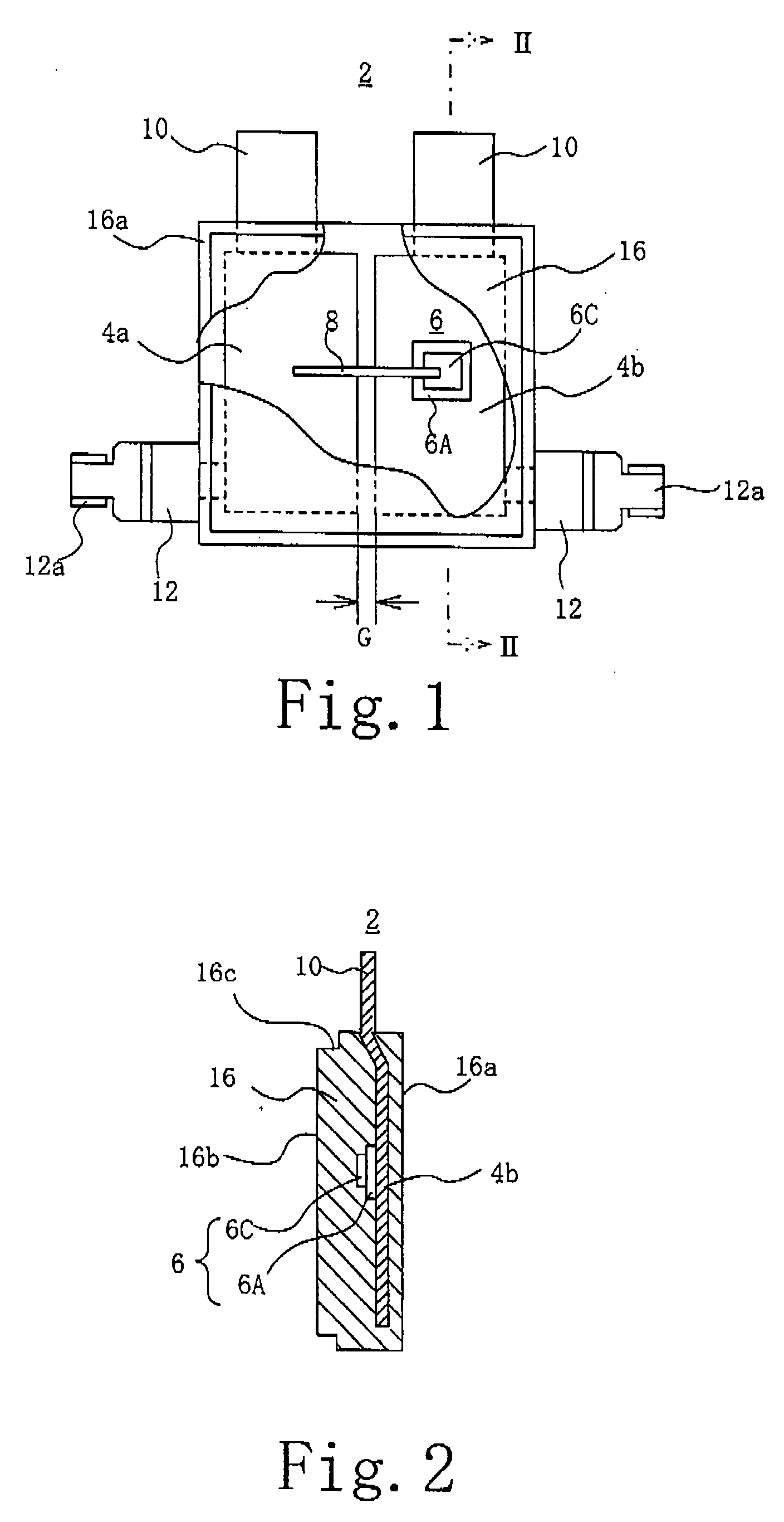
[0017] A solar cell module connector 1 according to the present invention includes a diode module 2 like the one shown in FIG. 1. The diode module 2 has plural, e.g. two, heat dissipating plates 4a and 4b. The heat dissipating plates 4a and 4b are rectangular metal plates having a thickness of 1 mm or more, and are spaced from each other with their longer side disposed in parallel, with a spatial insulation gap G disposed between them. A bypass diode, e.g. a thin plate diode chip 6, has its anode 6A soldered to the surface of the heat dissipating plate 4b. The diode chip 6 has its cathode 6C connected to the surface of the heat dissipating plate 4a via a connecting conductor 8. Slits may be desirably formed to surround the four corners of the anode of the diode chip 6. The slits are useful in positioning the diode chip 6 in place and in dispersing thermal stress caused by heat generated by the diode chip 6.

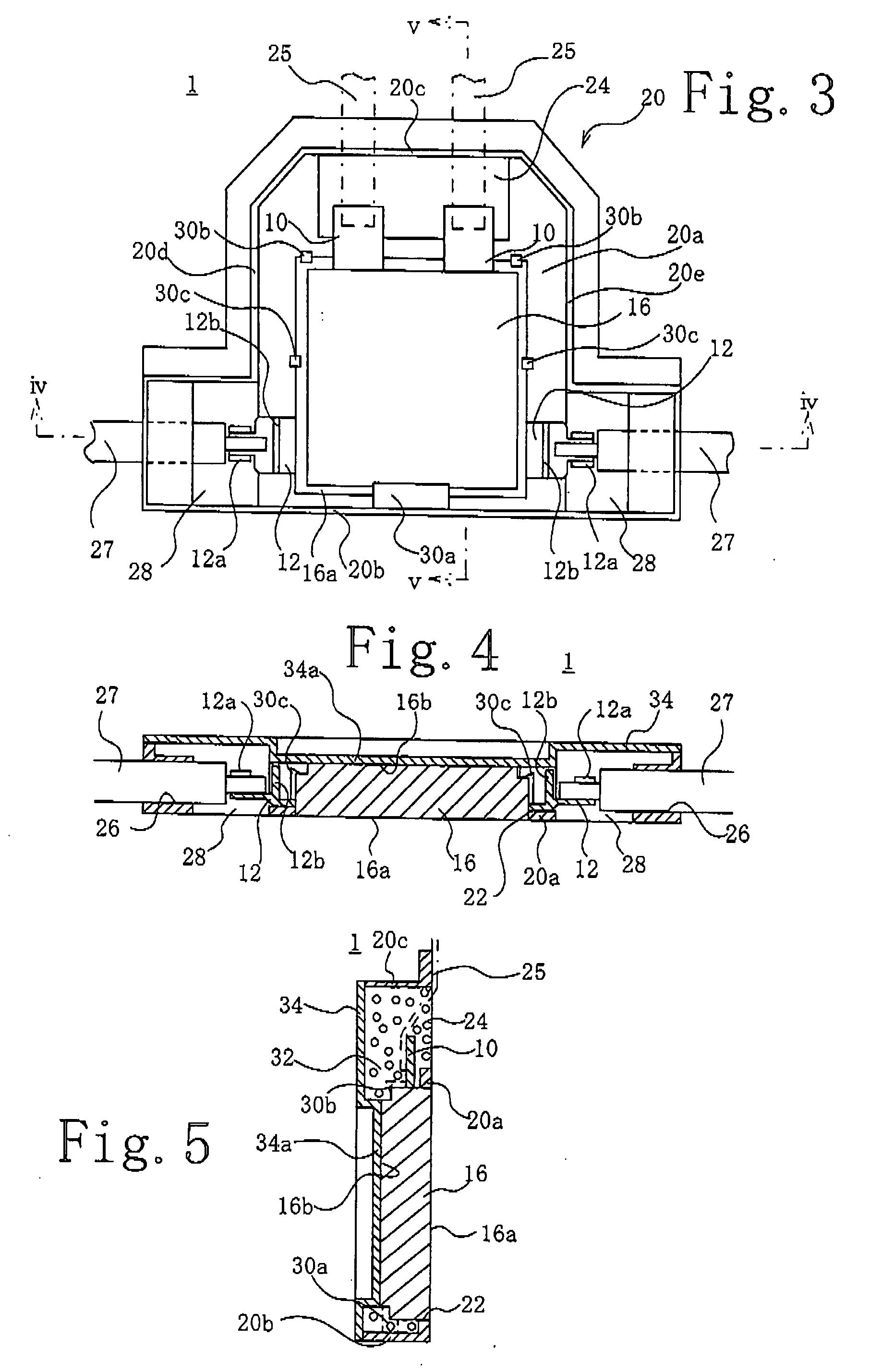
[0018] Terminals 10 for connection to solar cell module leads are formed to e...

second embodiment

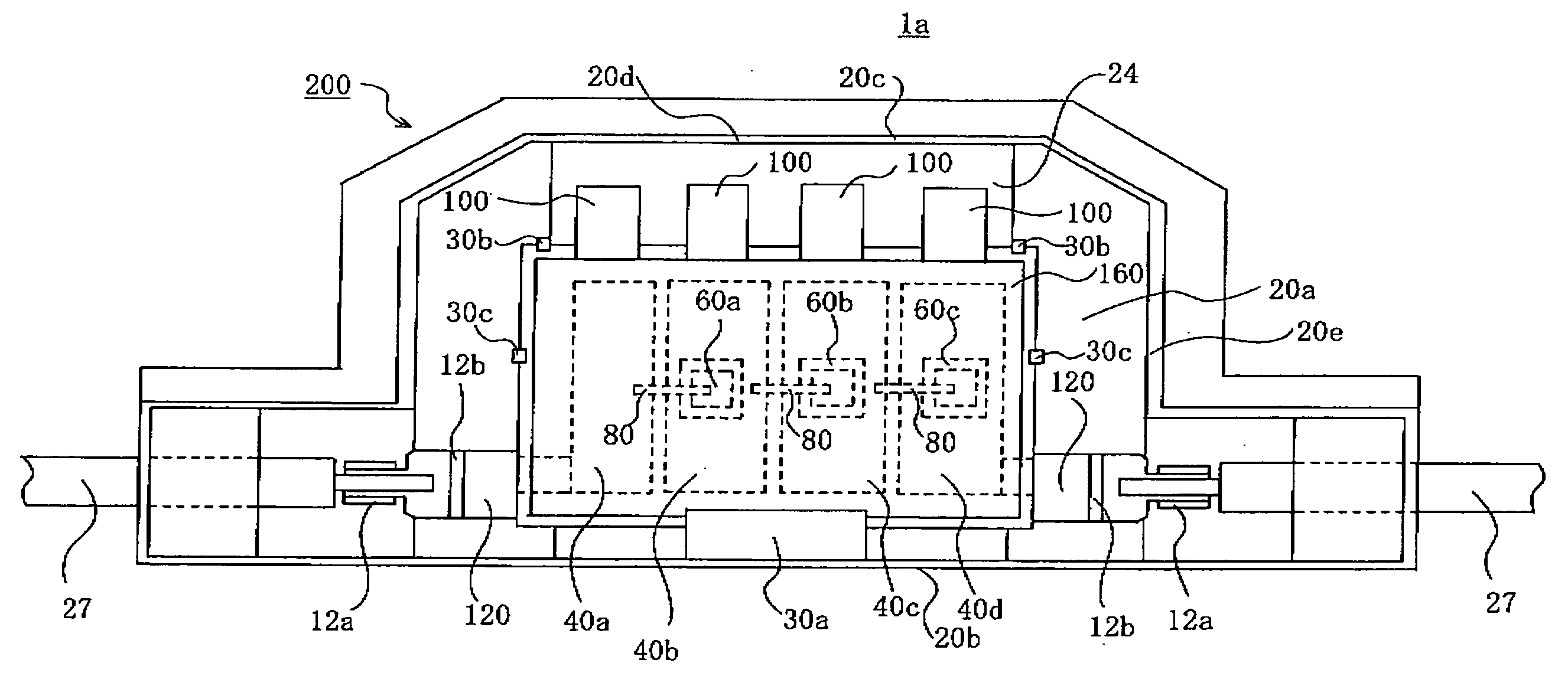
[0032] Adjacent two of the terminals 100 of the connector 1a are adapted to be connected to the respective ends of each of three serially connected solar cell modules (not shown), whereby each of the three solar cell modules is connected in parallel with an individual one of the diode chips 60a-60c. The heat dissipating plates 40a-40d of the connector 1a are formed to have the same size, but no diode chip is disposed on the heat dissipating plate 40a, and, therefore, the amounts of heat dissipated through the heat dissipating plates 40a-40d are not equal. Accordingly, it is desirable to form the heat dissipating plates in such a manner that the heat dissipating plate with a diode mounted thereon, which can dissipate least heat into the surroundings and, therefore, would become hot if no measures are taken against it, has the largest width, the heat dissipating plates with a diode mounted thereon which can dissipate more heat into the surroundings have successively smaller widths, a...


PUM


Abstract

[Subject] To provide a thin solar cell module connector having improved reliability, enduring long use, and having high productivity. [Means to Realize the Subject] A diode chip 6 is disposed in a diode module 2. The diode module 2 is transfer-molded. The diode module 2 is fitted in an opening 22 in the module box 20.

Description

TECHNICAL FIELD [0001] This invention relates to a solar cell module connector and, more particularly, to such solar cell connector having a diode for bypassing a solar cell module. BACKGROUND [0002] Connectors are used for connecting a plurality of solar cell modules in series at a site where such solar cell modules are installed. Some types of such connectors have a built-in bypass diode for bypassing a solar cell module. Technical attempts to improve the connectors have been made to make them small in thickness. For example, Japanese Patent No. 3,498,945 discloses in its specification a technique, according to which a bare chip diode, which is not provided with a protective package and, therefore, bare, is used, and, when a box of a solar cell module connector is filled with resin, the bare chip diode is also packaged together. According to this technique, however, when a solar cell module with which a connector is connected in parallel is not generating electric power, current f...

Claims


Application Information

Patent Timeline
Patent Type & Authority Applications(United States)
IPC IPC(8): H01L31/05
CPCH01R9/2425H01R13/5216H02S40/345H02S40/34H01R13/6641Y02E10/50
Inventor AOYAMA, MASAHIROMATSUYOSHI, KATSUNOBUSAITO, KOICHIINAMI, KAZUNORI
Owner SANSHA ELECTRIC MFG
Why Eureka
Try Eureka