Cup tool, cup tool cup and method of using the cup tool

Active Publication Date: 2008-01-17
WELLS FARGO BANK NAT ASSOC +1
View PDF1 Cites 5 Cited by
  • Summary
  • Abstract
  • Description
  • Claims
  • Application Information

AI Technical Summary

Benefits of technology

[0009] It is therefore an object of the invention to provide a cup tool that is simple a

Problems solved by technology

The fluids are generally corrosive and/or abrasive because t

Method used


Image

  • Cup tool, cup tool cup and method of using the cup tool
  • Cup tool, cup tool cup and method of using the cup tool
  • Cup tool, cup tool cup and method of using the cup tool

Examples


Embodiment Construction

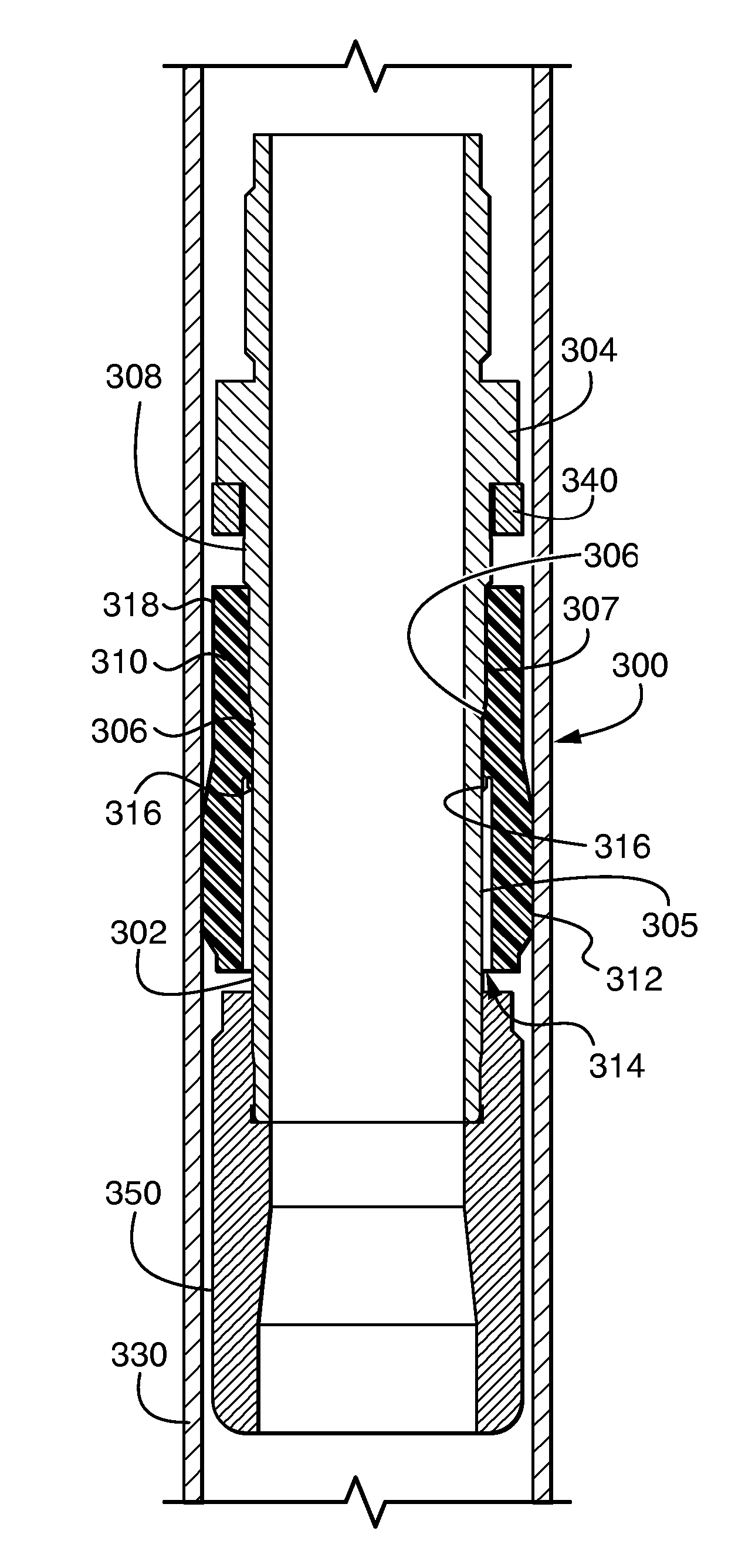
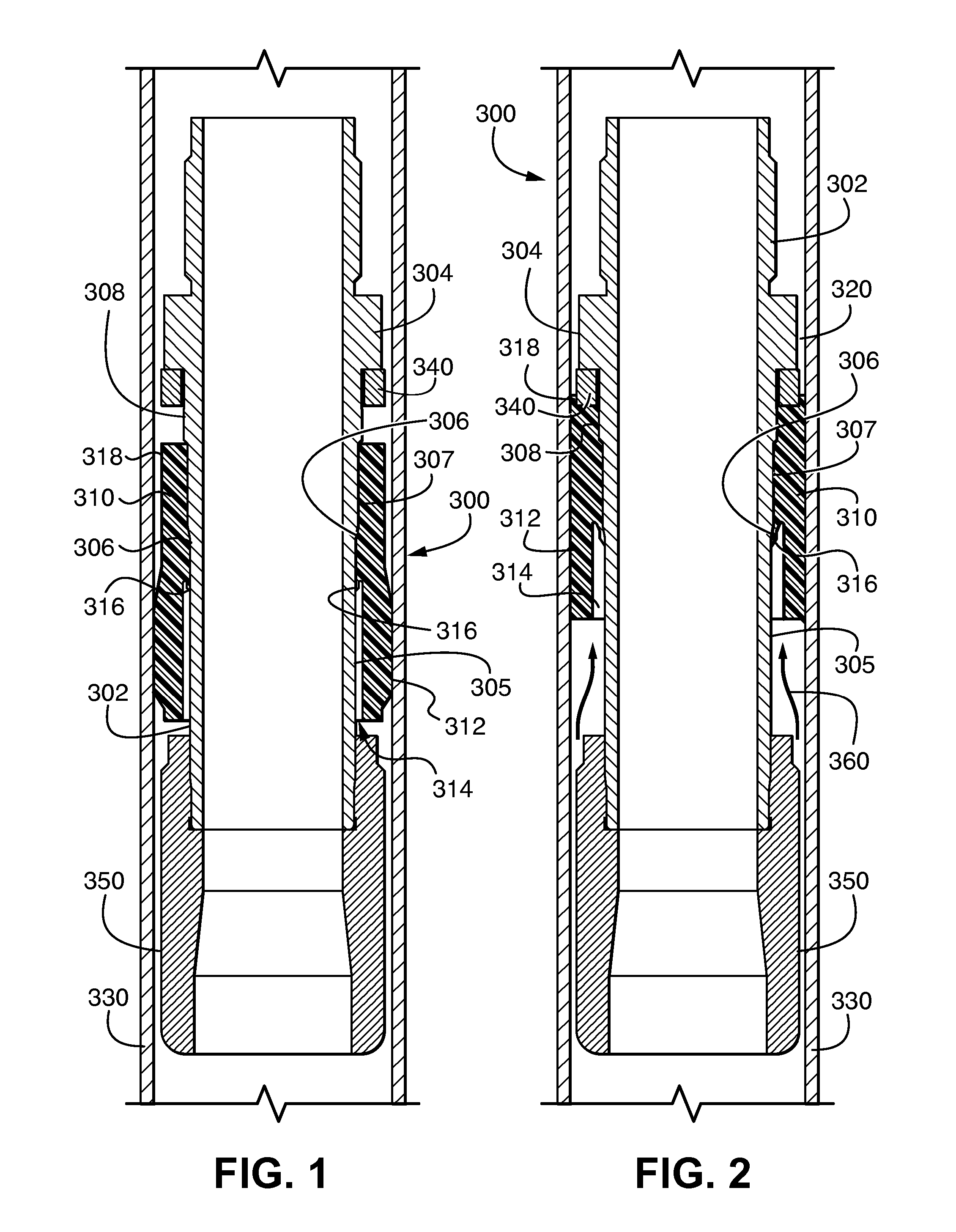
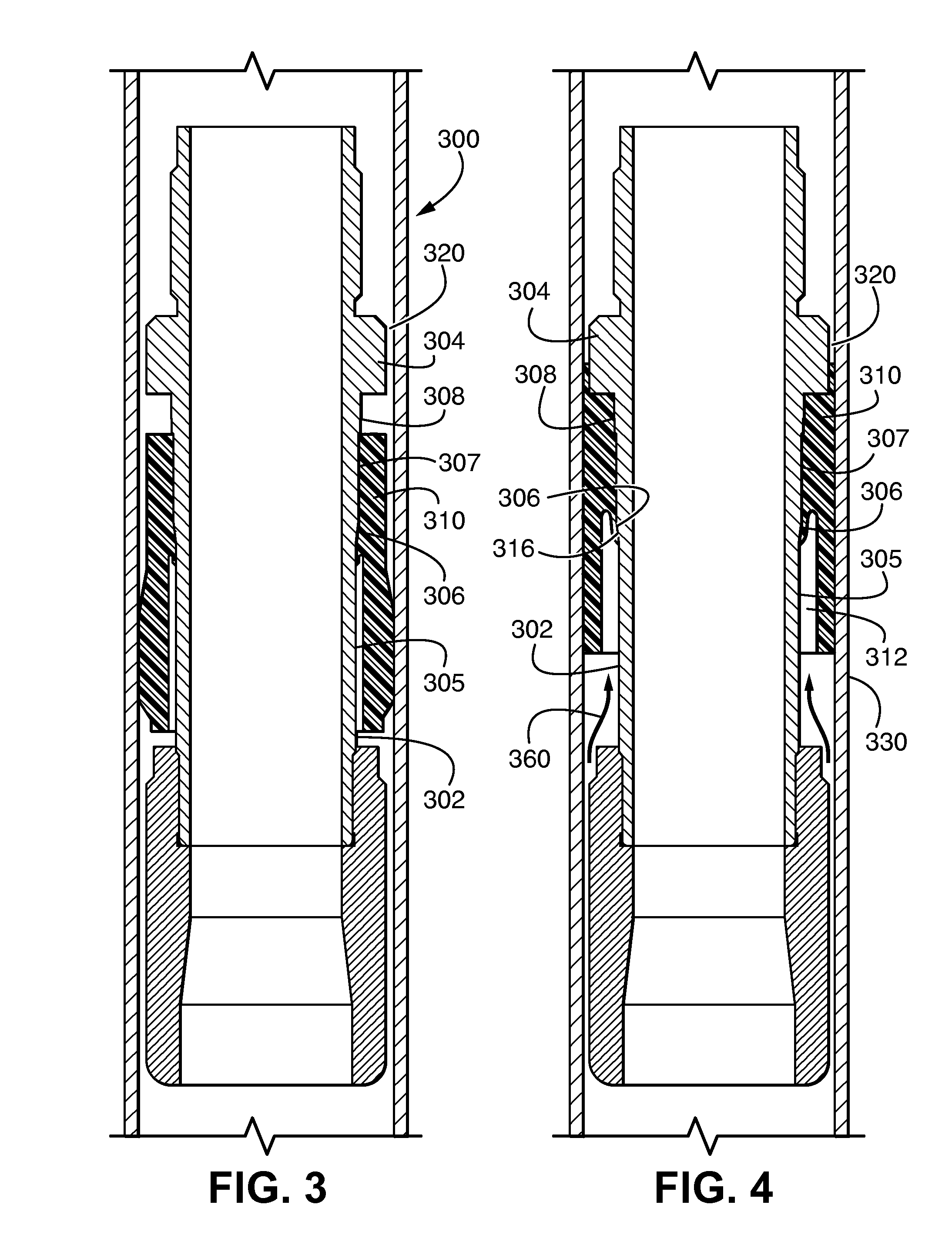
[0031] In general, as will be explained below, the invention provides a cup tool for providing a high-pressure fluid seal in an annular gap between a high-pressure mandrel and a casing or a production tubing in a wellbore. The cup tool includes a cup tool tube having a threaded upper end for connection to the high-pressure mandrel, an elastomeric cup that is slidably received on a cup tool tube. A top end of the elastomeric cup is forced upwardly and over an annular shoulder at the top to the cup tool tube to a set position when the cup is exposed to elevated fluid pressures, thereby extruding into the annular gap to provide the high-pressure fluid seal. In the set position, a lip seal on an internal surface of the cup sealingly engages a tapered external surface of the cup tool tube to provide a high-pressure fluid-tight seal between the elastomeric cup and the cup tool tube. A bullnose, or the like, is threadedly fitted to a bottom of the cup tool tube to protect the cup while gui...


PUM


Abstract

A cup tool includes a cup tool tube having a threaded upper end for connection to a high-pressure mandrel, an outer surface over which an elastomeric cup is slidably mounted for reciprocal movement from an unset position for entry into a wellbore to a set position in which an annular gap is obstructed to contain fluid pressure below the elastomeric cup. The outer surface of the cup tool tube has a lower region of a first diameter and an upper region with a second, larger diameter and a tapered region between the upper region and the lower region. The elastomeric cup includes a lip seal that rides against the outer surface of the cup tool tube, and seals against the tapered region of the cup tool tube to provide a high pressure seal between the cup tool tube and the elastomeric cup in the set position.

Description

CROSS-REFERENCE TO RELATED APPLICATIONS [0001] This application is a continuation-in-part of U.S. patent application Ser. No. 10 / 979,414 filed Nov. 2, 2004.MICROFICHE APPENDIX [0002] Not applicable. FIELD OF THE INVENTION [0003] This invention generally relates to wellhead isolation equipment and, in particular, to a cup tool for use with wellhead isolation equipment. BACKGROUND OF THE INVENTION [0004] Most oil and gas wells require stimulation to enhance hydrocarbon flow to make or keep them economically viable. The servicing of oil and gas wells to stimulate production requires the pumping of fluids into the well under high pressure. The fluids are generally corrosive and / or abrasive because they are laden with corrosive acids and / or abrasive proppants. [0005] In order to protect components that make up the wellhead, such as the valves, tubing hanger, casing hanger, casing head and blowout preventer equipment, wellhead isolation equipment, such as a wellhead isolation tool, a casi...

Claims


Application Information

Patent Timeline
IPC IPC(8): E21B33/12
CPCE21B33/126
Inventor MCGUIRE, BOBARTHERHOLT, DANNY LEE
Owner WELLS FARGO BANK NAT ASSOC
Why Eureka
Try Eureka