Drive control apparatus for forklift

a control apparatus and forklift technology, applied in the direction of gearing, pedestrian/occupant safety arrangement, tractors, etc., can solve the problems of limiting the increase of engine speed, preventing the efficiency of loading operation from being degraded, and reducing so as to ensure the stability of the vehicle and improve the workability of loading operation.

Active Publication Date: 2008-01-17
TOYOTA IND CORP
View PDF6 Cites 19 Cited by
  • Summary
  • Abstract
  • Description
  • Claims
  • Application Information

AI Technical Summary

Benefits of technology

[0005] Accordingly, it is an objective of the present invention to provide a drive control apparatus for a forklift that, in the case where a loading device is actuated during driving with a speed limit, ensures the stability of the vehicle while improving the workability of the loading operation.

Problems solved by technology

A speed limit is set for each of the outdoor and indoor driving modes, thereby limiting increase of the engine speed.
Thus, since increase of the engine speed is suppressed so that the vehicle speed does not exceed the speed limit in a forklift that limits the driving of the vehicle (vehicle speed), loading operation (actuation of the loading device) needs to be performed with a lowered engine power while the speed is limited, which can degrade the efficiency of the loading operation.
In this respect, the technique disclosed in the publication No. 2000-179372 cancels the limitation on the driving during the loading operation, thereby preventing the efficiency of the loading operation from being degraded.
Therefore, the stability of the vehicle can be degraded by a sudden acceleration.

Method used


Image

  • Drive control apparatus for forklift
  • Drive control apparatus for forklift
  • Drive control apparatus for forklift

Examples


second embodiment

[0080] A second embodiment of the present invention will now be described with reference to FIGS. 10 and 11. In the following embodiments, explanations of the same components of the already described embodiment will be omitted or simplified.

[0081] In this embodiment, at step S21 of the mode switching process shown in FIG. 9, the detection that the driving state is the driving force disconnection state is performed by detecting the clutch pressure of the pressure receiving chambers 42a, 43a of the advancing clutch 42 and the reversing clutch 43.

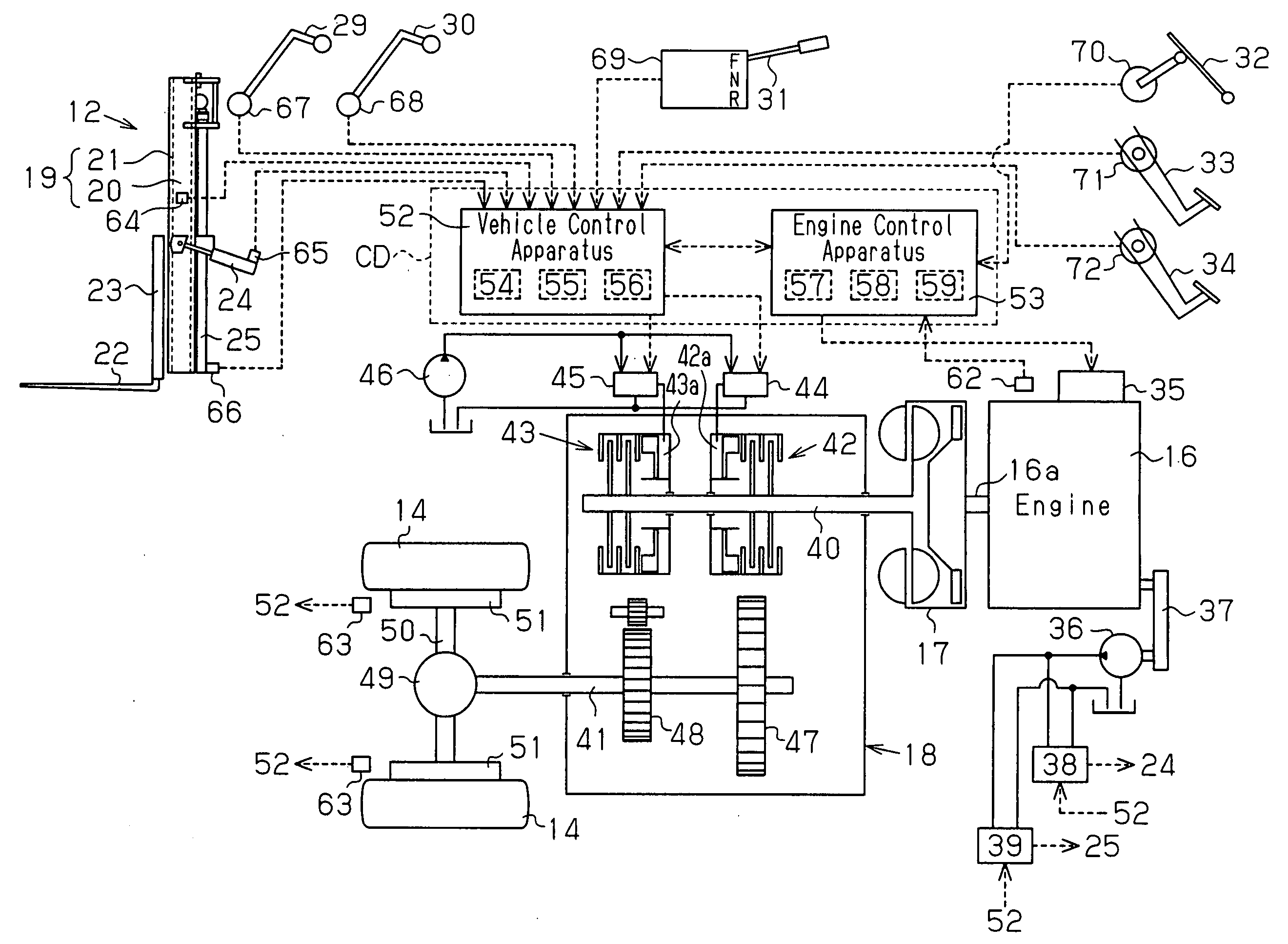
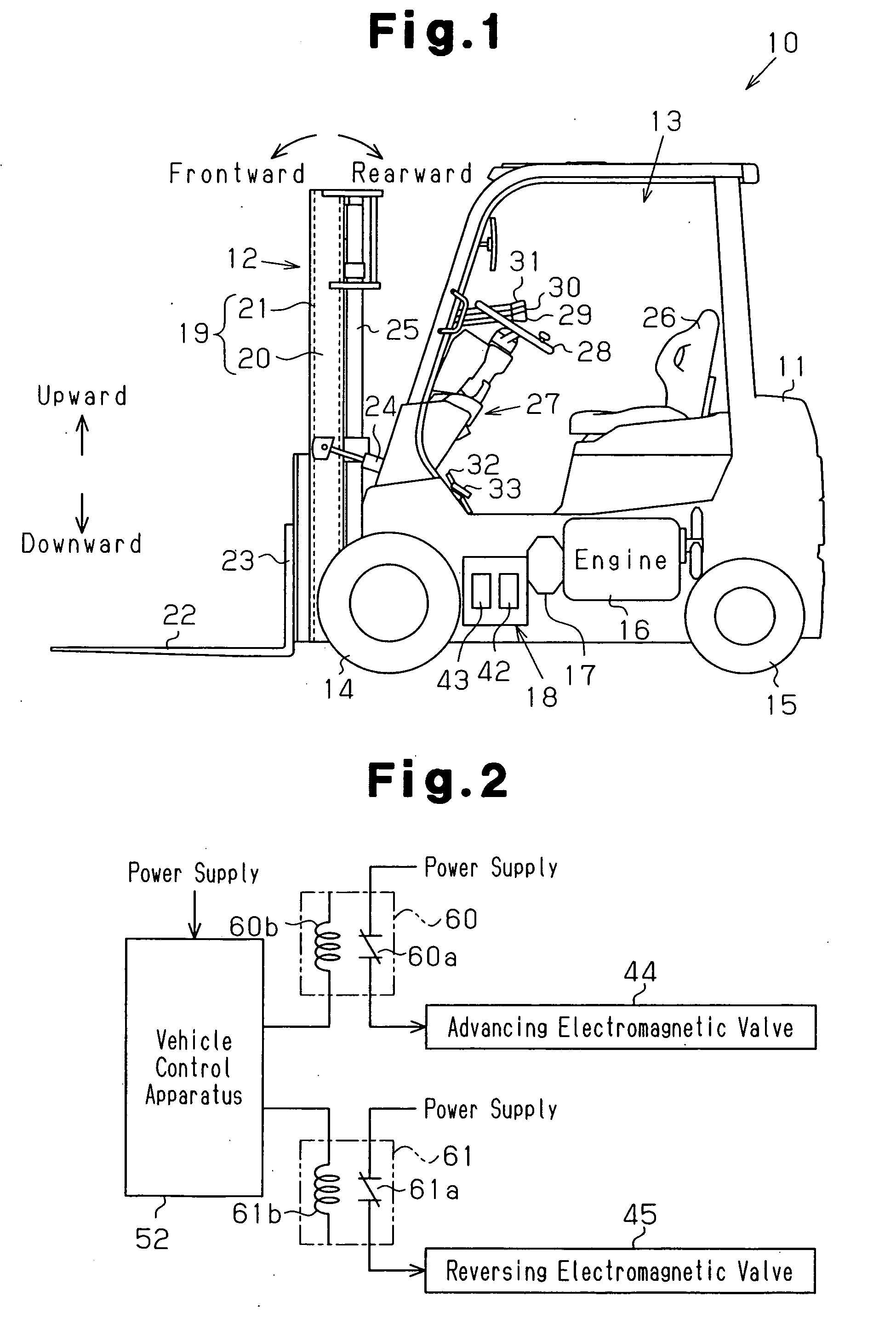
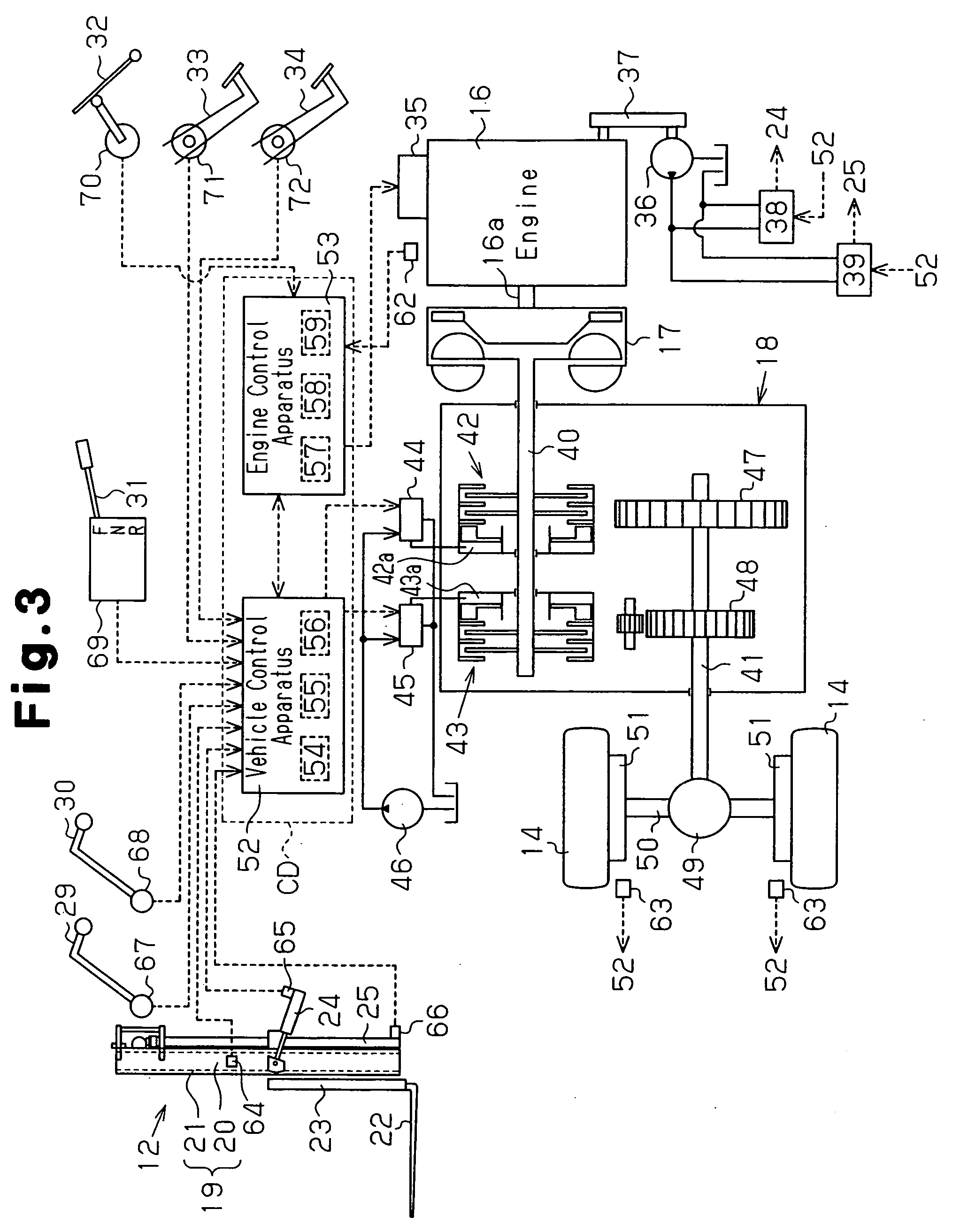
[0082] The structure of the forklift 10 of this embodiment will now be described with reference to FIG. 10. FIG. 10 mainly shows differences from the forklift 10 described in the first embodiment (shown in FIG. 3). The components (structure) that are not shown in FIG. 10 are the same as those of the forklift 10 shown in FIG. 3.

[0083] As shown in FIG. 10, clutch pressure sensors 80, 81 are provided at the advancing clutch 42 and the reversin...

third embodiment

[0089] A sixth embodiment of the present invention will now be described with reference to FIGS. 3 and 8. This embodiment may be applied to the first and second embodiments.

[0090] In this embodiment, when the load state is changed while the forklift 10 is traveling, and the contents of limitation on the vehicle driving (the maximum vehicle speed value and the acceleration / deceleration value) are changed depending on the change of the load state, a control for suppressing a sudden change in the vehicle speed (acceleration and deceleration) is executed (hereafter, referred to as normalizing control). Changes in the load state include a case where the fork height is changed from a low fork height to a high fork height or from a high fork height to a low fork height, and a case where the tilt angle is changed from the rearward tilt range to the outside of the range or from the outside of the range into the range. In this embodiment, the CPU 57 of the engine control apparatus 53 execute...


PUM


Abstract

When a determination result of a limitation determining section during a driving of a forklift is positive, a control section limits a vehicle speed and adjusts an engine speed. If a limitation canceling condition is met while the vehicle speed is limited, a control section cancels a vehicle speed limitation state, and executes a loading priority control in which an actuation of a loading device is prioritized. Thus, when a loading device is actuated during driving with a speed limit, the stability of the forklift is ensured while improving the workability of the loading operation.

Description

BACKGROUND OF THE INVENTION [0001] The present invention relates to a drive control apparatus for controlling driving of a forklift. [0002] Conventionally, forklifts are widely used as industrial vehicles for handling loads (picking up and placing of loads) in plants. Due to its characteristic usage, the driving stability of this type of forklift greatly varies depending on the load state. For example, the center of gravity of the vehicle is shifted and the driving stability varies between a state of carrying no loads and a state of carrying a load. When carrying a load, the driving stability varies depending on the weight of the load, the height of the fork on which the load is mounted, the tilt angle of the fork. Thus, conventionally, a technique for limiting the driving of a forklift to improve the driving stability of the vehicle is disclosed in Japanese Laid-Open Patent Publication Nos. 2001-31391 and 2000-179372. The technique disclosed in the publication No. 2001-31391 limits...

Claims


Application Information

Patent Timeline
Patent Type & Authority Applications(United States)
IPC IPC(8): B60L8/00F16H37/02
CPCB60W10/02B60W10/06B60W10/30F16H2059/6807B60W2510/0208B66F17/003B60W50/087Y02T10/7072B60W30/146B66F9/24B66F9/06
Inventor OKA, HIDENORIYAMADA, TADASHIKAMIYA, TOSHIKAZU
Owner TOYOTA IND CORP
Why Eureka
Try Eureka