Card dispenser adjustable subject to the size of the cards to be dispensed

a card dispenser and card size technology, applied in the direction of instruments, instruments, instruments, etc., can solve the problems of lowering detection accuracy, increasing material and manufacturing costs, and unable to function normally in the bill or card dispenser field

Inactive Publication Date: 2008-01-17
INT CURRENCY TECH
View PDF6 Cites 46 Cited by
  • Summary
  • Abstract
  • Description
  • Claims
  • Application Information

AI Technical Summary

Benefits of technology

[0009]According to another aspect of the present invention, the base member is detachably inserted into the card dispenser. Further, detection devices are respectively mounted in the dispenser body and the base member for detecting accurate dispensing of every card through the delivery path to the output port. After a long use of the card dispenser, the user can conveniently take the base member out of the dispenser body for cleaning. When a wrinkled card jammed in the delivery path, the user can take the base member out of the dispenser body conveniently and then remove the jammed card.

Problems solved by technology

Preparing different specifications of bill or card dispensers in order to fit different sizes of bills or cards greatly increases the material and manufacturing cost as well the inventory cost.
Further, after a long use of a bill or card dispenser, the authentification device of the bill or card dispenser tends to be contaminated by the dirt carried on the dispensed bills or cards or covered with dust in air, thereby lowering the detection accuracy or resulting in an error action.
Further, a bill or card dispenser may be unable to function normally when a wrinkled bill or card jammed in it.
However, because a number of screws are used to affix the bill or card dispenser to the housing of the bill exchanger or card / ticket vending machine, it is complicated to dismount the bill or card dispenser.
During the dismounting work, the worker must pick up every unfastened screw carefully because the loss of one screw results uninstallability of the bill or card dispenser.

Method used


Image

  • Card dispenser adjustable subject to the size of the cards to be dispensed
  • Card dispenser adjustable subject to the size of the cards to be dispensed
  • Card dispenser adjustable subject to the size of the cards to be dispensed

Examples


Embodiment Construction

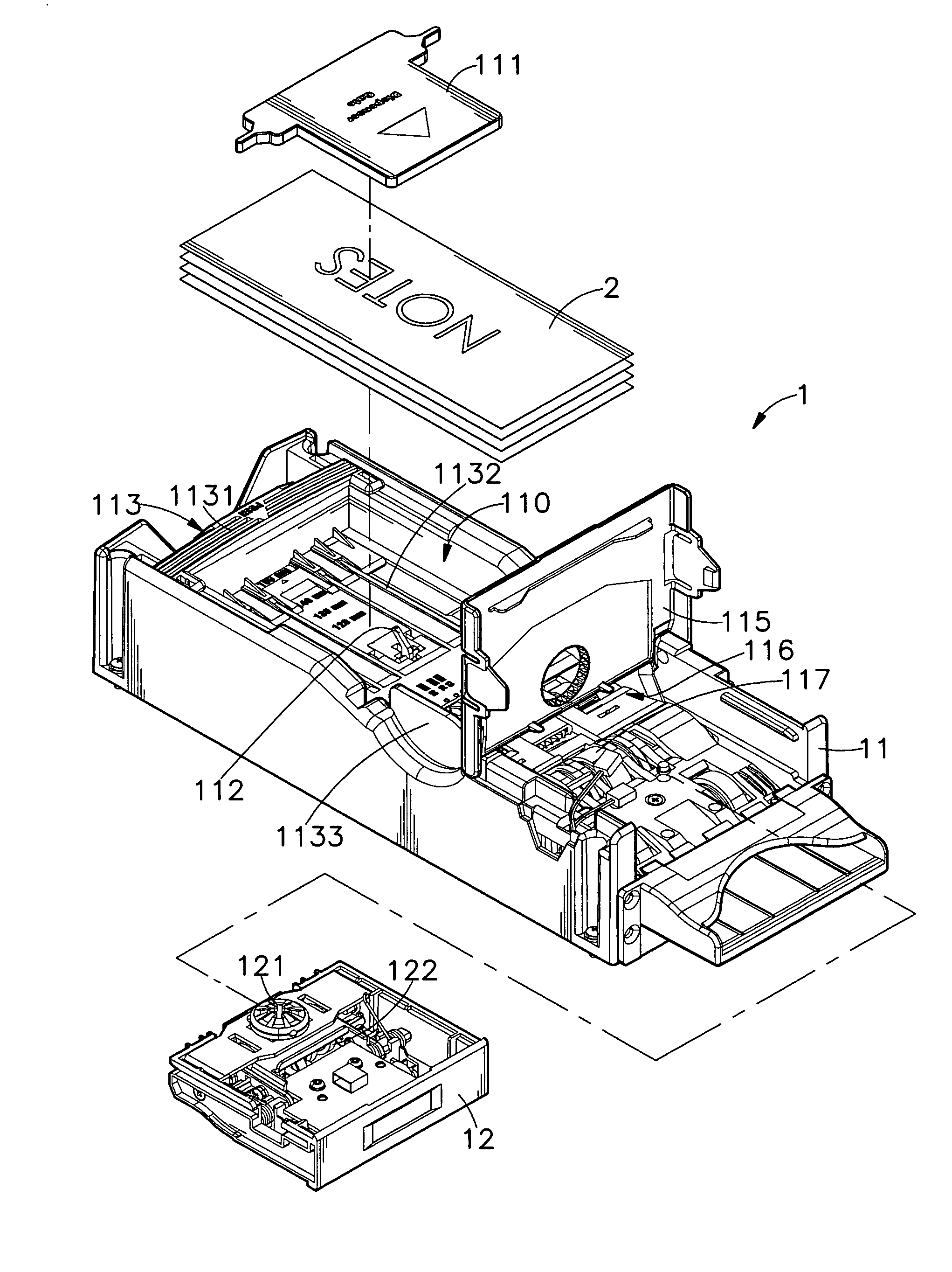
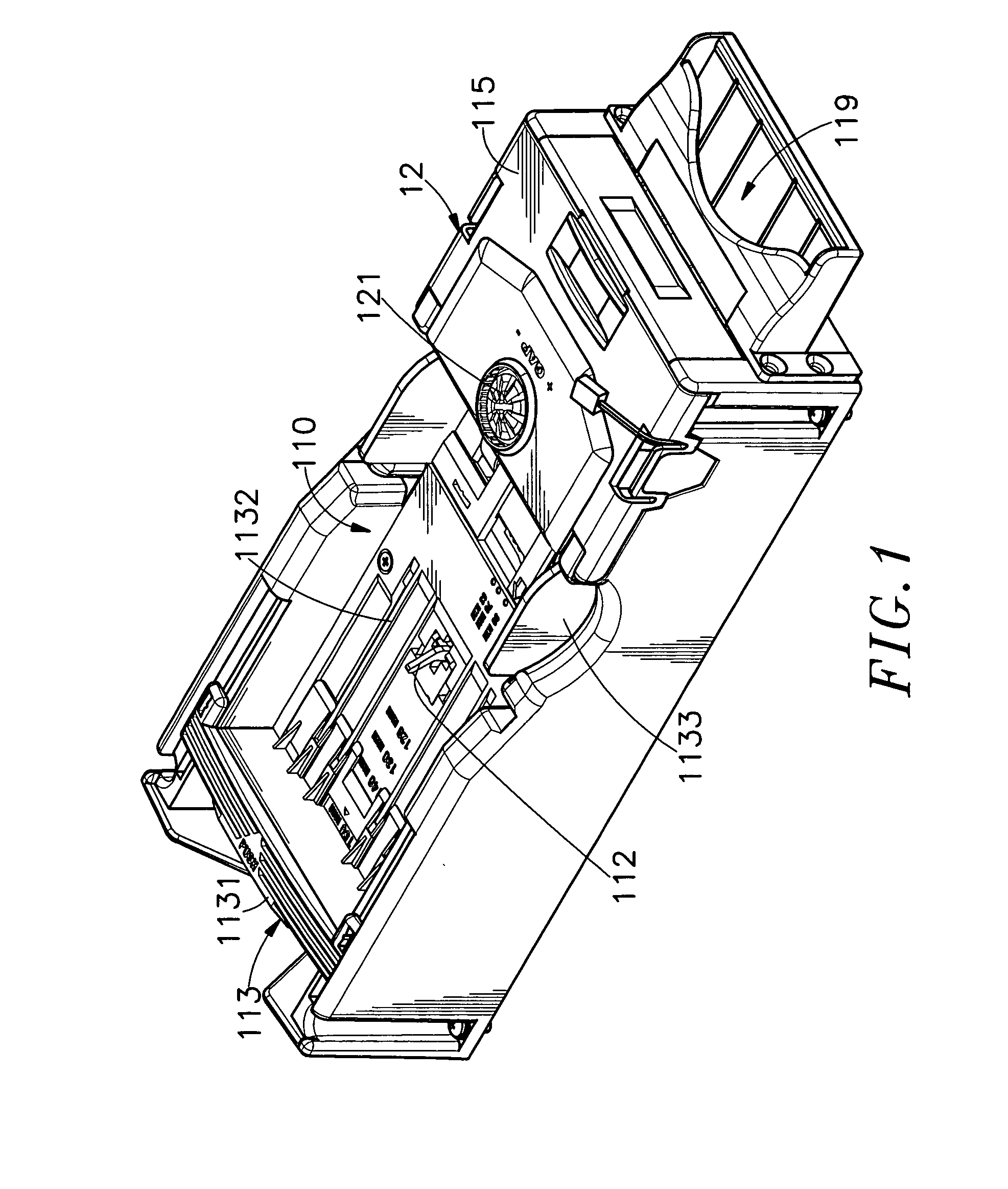
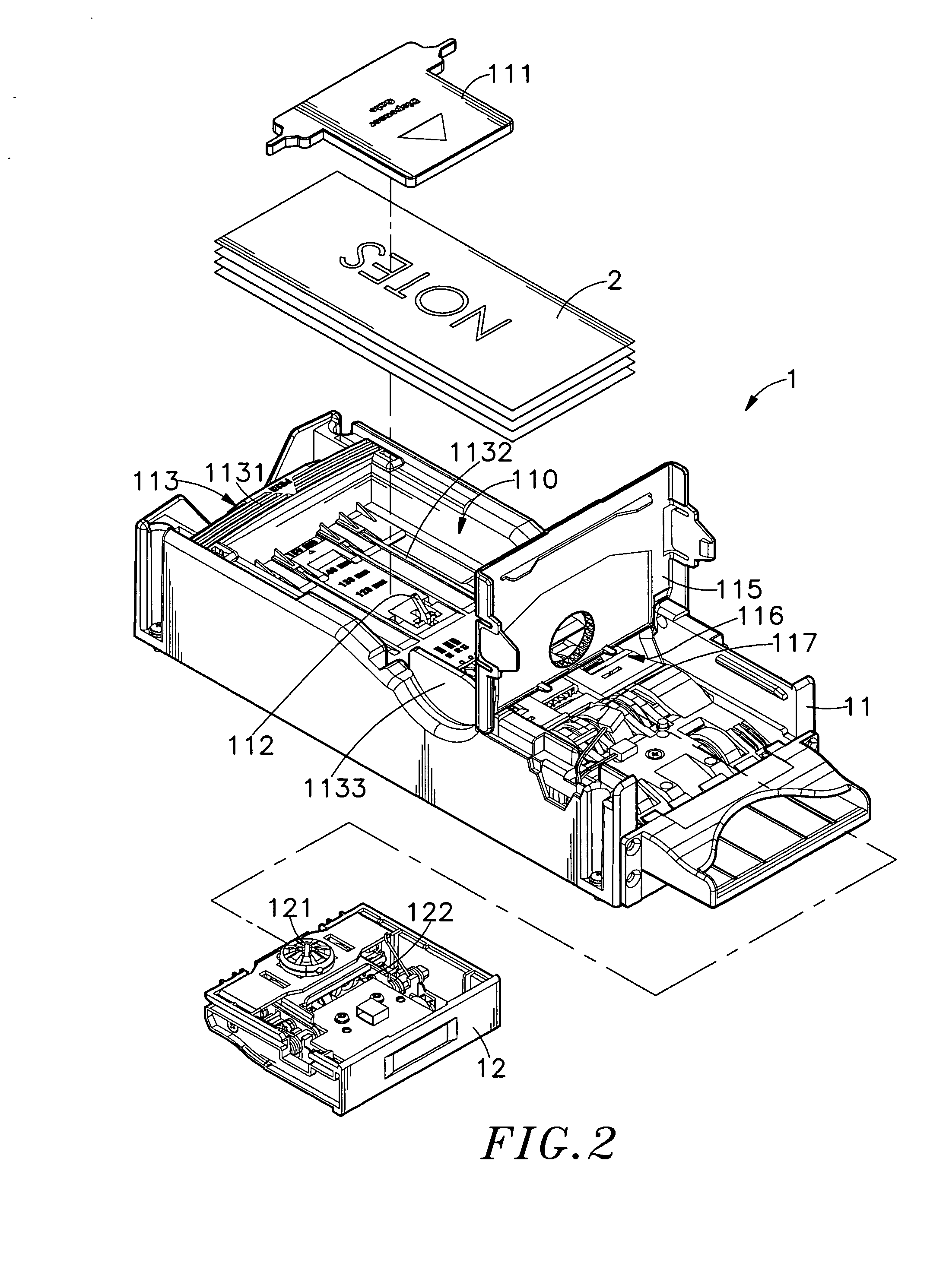
[0025]Referring to FIGS. 1, 2, 2A, 2B, and 2C, a card dispensers in accordance with the present invention is shown comprised of a dispenser body 11 and a base member 12.

[0026]The dispenser body 11 has an accommodation chamber 110 adapted to accommodate cards (or tickets or notes) 2, a pressure board 111 for holding down cards 2 in the accommodation chamber 10, a card sensor 112 mounted inside the accommodation chamber 110 and adapted to detect the presence of card or cards 2, an adjustment structure 113 adapted to adjust the length and width of the accommodation chamber 110 subject to the size of the cards 2 to be received, a conveying unit 114 provided in the accommodation chamber 110 at one side, a cover plate 115 provided in the accommodation chamber 110 adjacent to the conveyer unit 114, a delivery path 116 defined in the accommodation chamber 110 at one side, at least one roller 117 and one detection device 118 arranged in the delivery path 116. The conveying unit 114 comprises...


PUM


Abstract

A card dispenser is disclosed to include a dispenser body, which has an accommodation chamber for receiving a stack of cards for dispensing, an output port, and a delivery path connected between the accommodation chamber and the output port, a conveying unit controllable to deliver the cards from the accommodation chamber through the delivery path to the output port individually, an adjustment structure for adjusting the length and width of the accommodation chamber subject to the size of the loaded cards, a base member detachably mounted in the dispenser body and provided with an adjustment device for adjusting a gap of the delivery path subject to the thickness of the cards in the accommodation chamber, and detection devices respectively mounted in the dispenser body and the base member for detecting accurate dispensing of every card through the delivery path to the output port.

Description

BACKGROUND OF THE INVENTION[0001]1. Field of the Invention[0002]The present invention relates to automatic vending machines and more specifically, to a card dispenser for automatic vending machine, which is adjustable subject to the size of the cards to be dispensed and, which greatly saves the manufacturing cost and the inventory cost.[0003]2. Description of the Related Art[0004]Following fast development of information technology, non-shop business has become popular. Nowadays, various automatic vending machines are used everywhere to sell different products without servicemen. These automatic vending machines bring convenience to consumers and create new marketing routes for the suppliers.[0005]Further, an automatic vending machine has an exchanger on the inside for providing different products to the user after having received a bill. Following fast development of high technology, various advanced automatic vending machines such as ticket venders, bill exchangers, coin exchanger...

Claims


Application Information

Patent Timeline
Patent Type & Authority Applications(United States)
IPC IPC(8): G06F7/08G06K13/00
CPCG07F17/42G07F11/02
Inventor CHANG, HUNG-YI
Owner INT CURRENCY TECH
Why Eureka
Try Eureka