Rotary electric machine

a rotary electric machine and electric motor technology, applied in the direction of dynamo-electric machines, electrical appliances, cooling/ventilation arrangements, etc., can solve the problems of unnecessarily large rotary electric machines, limited output of rotary electric machines, and insufficient cooling system

Inactive Publication Date: 2008-01-17
KK TOSHIBA
View PDF12 Cites 35 Cited by
  • Summary
  • Abstract
  • Description
  • Claims
  • Application Information

AI Technical Summary

Problems solved by technology

While the cooling gas 7 contained in the closed frame 2 is driven to flow and circulate to cool the stator 3 and the rotor 4 in the above-described cooling system, such a cooling system may not be sufficient when the rotary electric machine 1 is a large capacity machine.
Thus, there is a problem that the dimensions and the flow rate of cooling gas to be used have to be designed for each rotary electric machine.
Additionally, when rotary electric machines of the same design are applied to different cooling water temperatures, there is a problem that the output of the rotary electric machine is limited due to the temperature limitation when the temperature of the cooling water that is actually supplied is higher than the design temperature of cooling water, whereas an unnecessarily large rotary electric machine has to be applied when the temperature of the cooling water that is actually supplied is lower than the design temperature of cooling water.
Still additionally, since rotary electric machines are generally designed to achieve the highest efficiency at the design point, there is a problem that the efficiency of the rotary electric machine decreases when it is driven to operate with a cooling water temperature that is different from the design temperature.

Method used


Image

  • Rotary electric machine
  • Rotary electric machine
  • Rotary electric machine

Examples


first embodiment

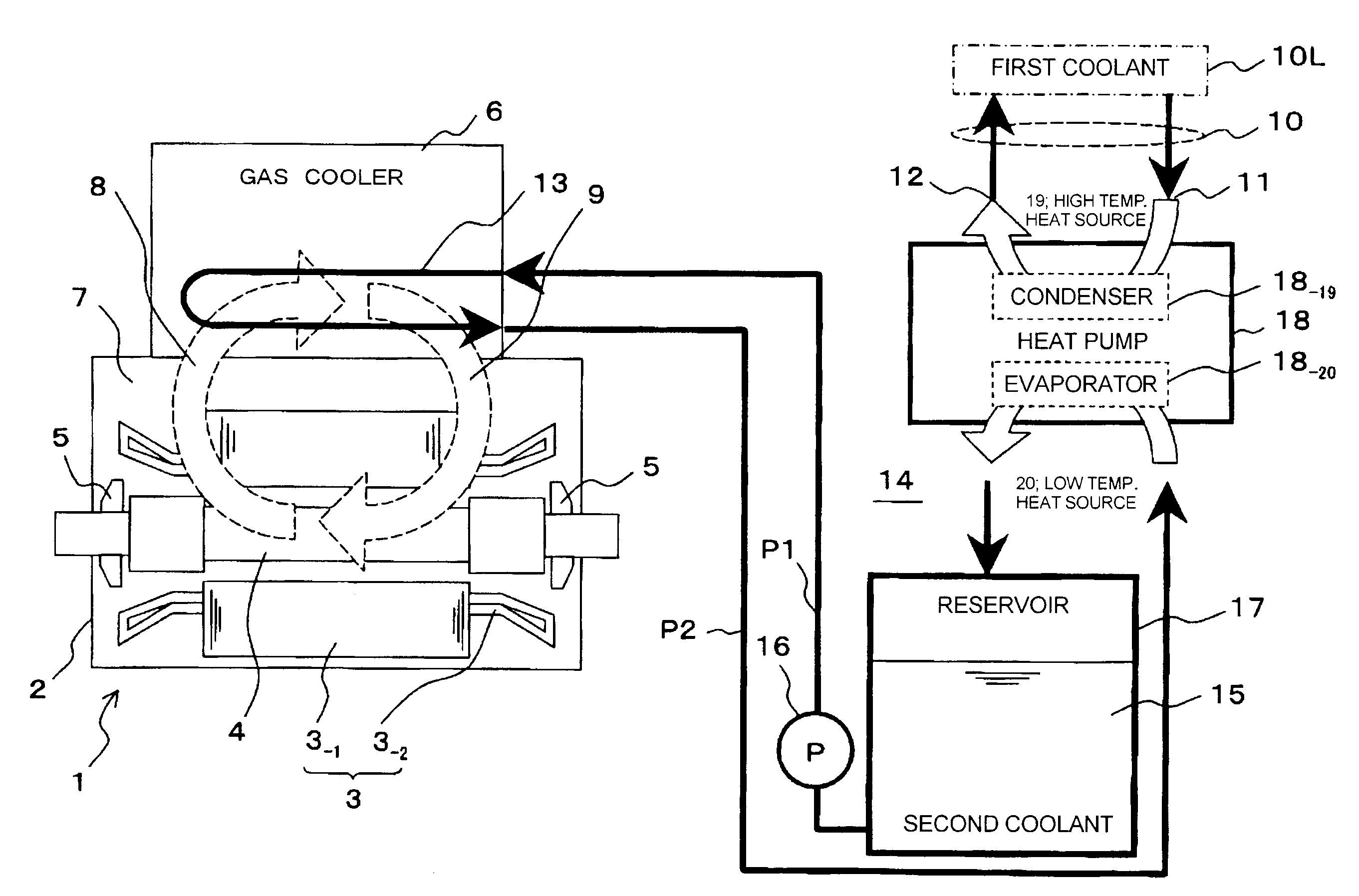
[0041]FIG. 1 is a schematic illustration of the first embodiment of a rotary electric machine according to the present invention.

[0042][Configuration]

[0043]In the conventional rotary electric machine described above by referring to FIG. 19, main cooling water 10L (to be referred to as the first coolant hereinafter for the purpose of convenience) is made to flow in the cooling tube 13 of the gas cooler 6 to cool cooling gas 7. In the present embodiment, a second coolant circulation system 14 for circulating liquid coolant such as cooling water to be used as intermediate coolant is connected. The intermediate coolant is prepared separately relative to the first coolant 10L in the cooling tube 13 of the gas cooler 6. A heat pump 18 is inserted between the second coolant circulation system 14 and the first coolant system 10. The second coolant 15 is cooled by means of a heat pump 18.

[0044]Although the underlying principle of a heat pump 18 is well known, it will be described briefly bel...

second embodiment

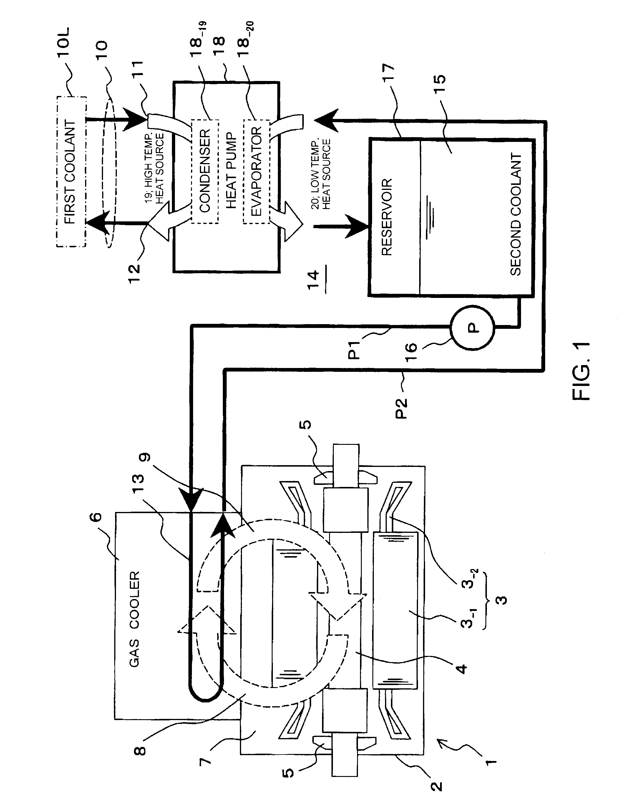
[0072]FIG. 2 is a schematic illustration of the second embodiment of a rotary electric machine according to the present invention.

[0073][Configuration]

[0074]The second embodiment of the present invention is characterized in that the second coolant circulation system 14 of the first embodiment is partly altered for this embodiment by dividing it into two circulation systems 21 and 22.

[0075]More specifically, the first system 21 is a gas cooler circulation system 21 where: the second coolant 15 stored in the reservoir 17 is led to the cooling tube 13 of the gas cooler 6 by way of the circulation pump 16a and the supply piping P1, and the second coolant 15 exchanges heat with high temperature cooling gas 8 in the cooling tube 13 before it is returned to the reservoir 17 by way of the return piping P2. The second system 22 is a heat pump circulation system 22 where: the second coolant 15 stored in the reservoir 17 is supplied to the evaporator 18-20 of the heat pump 18 by means of the c...

third embodiment

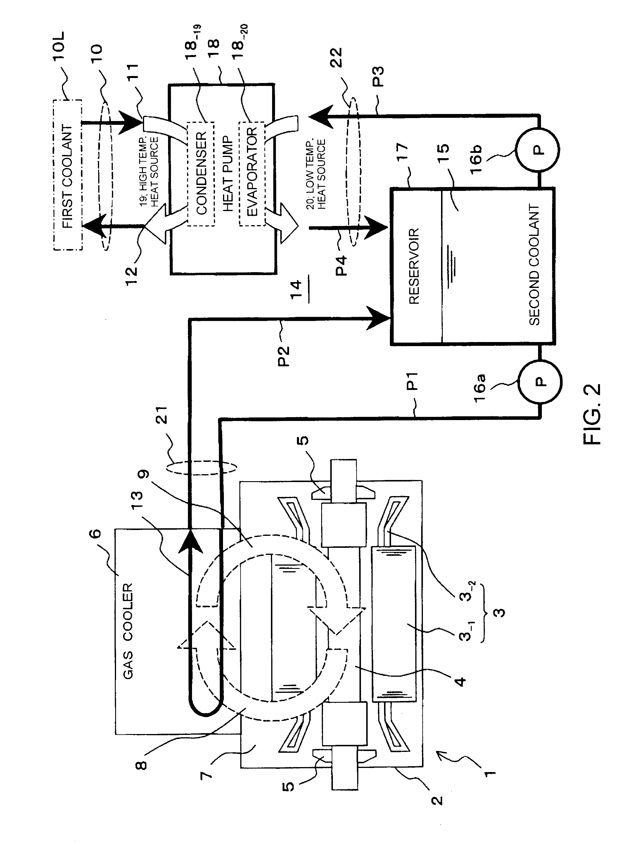
[0086]FIG. 3 is a schematic illustration of the third embodiment of a rotary electric machine according to the present invention.

[0087][Configuration]

[0088]The third embodiment of the present invention is characterized in that the second coolant circulation system 14 of the second embodiment is partly altered for this embodiment. More specifically, the supply piping P1 of the gas cooler circulation system 21 for circulating the second coolant 15 from the reservoir 17 storing the second coolant 15 to the gas cooler 6 and the supply piping P3 of the heat pump circulation system 22 for circulating the second coolant 15 from the reservoir 17 to the evaporator 18-20 of the heat pump 18 are connected to a common piping Pc1. The second coolant 15 in the two supply pipings P1 and P3 are pumped out by a common circulation pump 16.

[0089]Thus, the circulation pump 16 is inserted in the common piping Pc1 extending from the exit of the reservoir 17 to the junction point J of the supply pipings P...


PUM


Abstract

A rotary electric machine includes: a stator, a rotor and rotor fans contained in a closed type frame. The cooling gas is circulated in the frame by the rotor fans and warmed as a result of heat exchange with the stator and the rotor is cooled by a gas cooler. A heat pump is adapted to use cooling water or ambient air as high temperature heat source and liquid coolant as low temperature heat source. A liquid coolant circulation system for supplying liquid coolant to the heat exchange section of the gas cooler is provided. The liquid coolant is cooled by the heat pump and is supplied to the heat exchange section of the gas cooler by means of the coolant circulation system.

Description

CROSS REFERENCE TO RELATED APPLICATIONS[0001]This application is based upon and claims the benefit of priority from the prior Japanese Patent Application No. 2006-179589, filed on Jun. 29, 2006, the entire content of which is incorporated herein by reference.BACKGROUND OF THE INVENTION[0002]The present invention relates to a rotary electric machine such as a gas cooled generator. More particularly, the present invention relates to a rotary electric machine having an enhanced cooling effect.[0003]FIG. 19 schematically illustrates a cooling system of a closed type rotary electric machine.[0004]Referring to FIG. 19, reference numeral “1” denotes a closed type rotary electric machine which may typically be a turbine generator arranged in a closed type frame 2. The machine 1 comprises a stator 3 which includes an annular stator core 3-1 and a stator coil 3-2 contained in the slot of the stator core 3-1. The machine 1 further comprises a rotor 4 provided with a field coil (not shown) woun...

Claims


Application Information

Patent Timeline
Patent Type & Authority Applications(United States)
IPC IPC(8): H02K9/00H02K9/06H02K9/18H02K9/193
CPCH02K3/24H02K9/26H02K9/10
Inventor KABATA, YASUOYAMASHITA, KATSUYATANIYAMA, YOSHIHIROTOKUMASU, TADASHIKAKIUCHI, MIKIOMATSUYAMA, KOJI
Owner KK TOSHIBA
Why Eureka
Try Eureka