Image forming device and method of manufacturing the same

a technology of forming device and manufacturing method, which is applied in the direction of digitally marking record carriers, instruments, electrographic processes, etc., can solve the problems of reducing efficiency, requiring time to manufacture, and requiring considerable work to connect the large frames to each other, so as to achieve convenient temporary assembly, improve assembly operation, and simplify the assembly of the chassis

Inactive Publication Date: 2008-01-17
MURATA MASCH LTD
View PDF2 Cites 9 Cited by
  • Summary
  • Abstract
  • Description
  • Claims
  • Application Information

AI Technical Summary

Benefits of technology

[0010]With the above-described configuration, the first chassis and the second chassis can be vertically connected to each other easily without jigs. Accordingly, assembly of the chassis can be simplified, and an assembly operation can be improved.
[0012]With the above-described configuration, since excessive friction is not generated when inserting the first protrusion and the second protrusion into the recessed portion, the assembly operation can be further improved.
[0014]With the above-described configuration, when inserting the first and the second protrusions into the recessed portion, simultaneously, the control protrusion is gradually pressed by the latching protrusion, and then elastically deforms the plate-shaped arm so that the control protrusion can easily pass the latching protrusion. Accordingly, the assembly operation can be improved more.
[0016]With the above-described configuration, the first chassis and the second chassis can be reliably fixed by using the tapping screw. Further, since the tapping screw is preferably used, screw cutting at a hole in advance is not required, and it is convenient. Furthermore, when performing the screw cutting by the tapping screw, substantial force is applied onto the chassis, however, both of the chassis can prevent separation by the above-described connection structure. Thus, both of the chassis can be fixed by reliably performing the screw cutting.
[0018]With the above-described configurations, the first chassis and the second chassis can be vertically and temporarily assembled easily without jigs, and then can be fixed by the fixing member. Accordingly, the assembly of the chassis is simplified, and an assembly operation is improved.

Problems solved by technology

However, when assembling each of the frames, it requires considerable work to connect the large frames to each other.
Moreover, the frames can tumble during an assembly operation, requiring time to manufacture, and efficiency has often been reduced.
With this problem in mind, jigs etc. can be used for the assembly operation, however, it is hardly preferable since the cost of the jigs, securing of storage space for the jigs, and a moving operation of the jigs, etc. are additionally required.

Method used


Image

  • Image forming device and method of manufacturing the same
  • Image forming device and method of manufacturing the same
  • Image forming device and method of manufacturing the same

Examples


Embodiment Construction

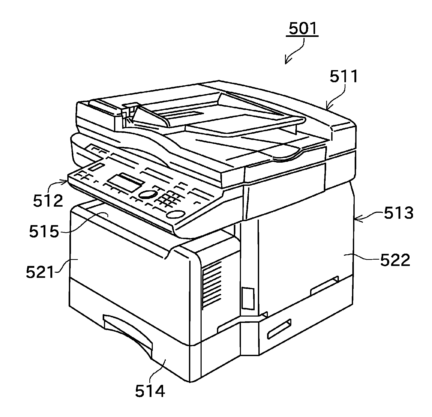
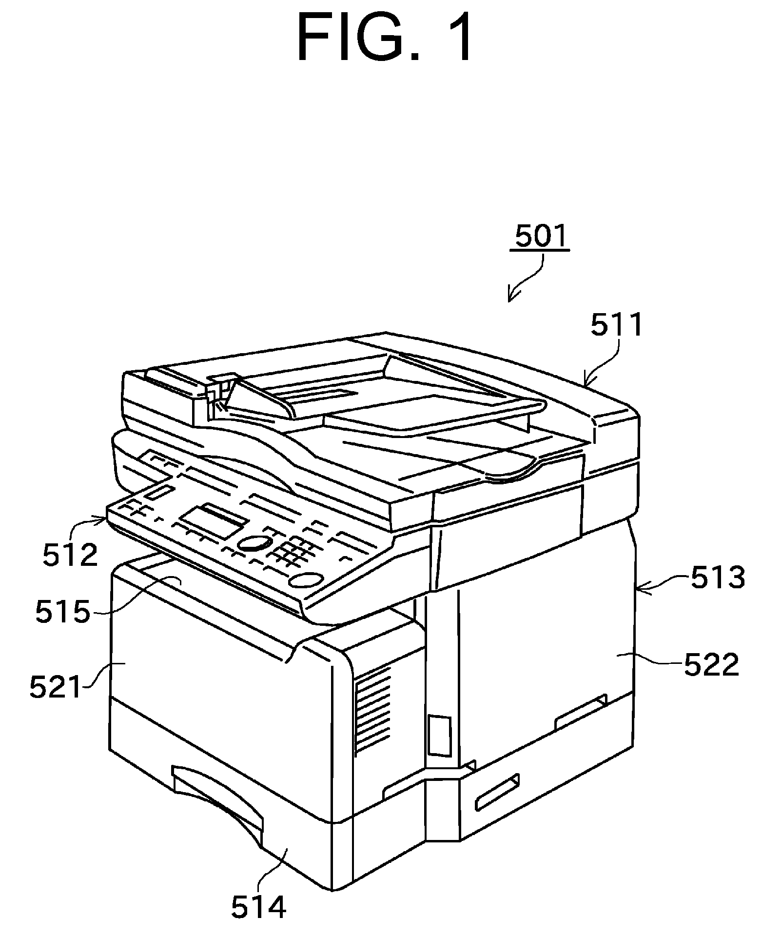
[0038]As illustrated in an external perspective view of FIG. 1, a copy-and-facsimile MFP 501 as an image forming device includes an image scanning unit 511, an operation panel 512, a main body 513, and a paper feed cassette 514. The image scanning unit 511 functions as a flatbed scanner and an auto document feed scanner. The operation panel 512 is used for instructing a number of copies and a facsimile destination etc. The main body 513 has an image forming unit, etc. which forms an image onto a paper as a recording medium. The paper feed cassette 514 sequentially supplies the paper.

[0039]The copy-and-facsimile MFP 501 includes a front cover 521 arranged on a front side (a side on which the operation panel 512 is provided) of the main body 513, and includes a jam access cover 522 arranged on one side surface of the main body 513. The front cover 521 and the jam access cover 522 can be opened and closed. For example, when performing maintenance, etc., an inside of the main body 513 c...


PUM


Abstract

In an image forming device, at an end portion of a middle frame, a first protrusion and a second protrusion are arranged so as to protrude substantially parallel to each other. A plate-shaped arm extends from a leading end of the second protrusion in a direction towards a leading end of the first protrusion. A control protrusion is integrally arranged at a leading end of the plate-shaped arm. On the other hand, a rear side frame has a recessed portion. When the first protrusion, the second protrusion, and the plate-shaped arm are inserted into the recessed portion, the control protrusion passes a latching protrusion provided to the recessed portion, and the control protrusion and the latching protrusion are latched by facing each other.

Description

BACKGROUND OF THE INVENTION[0001]1. Field of the Invention[0002]The present invention relates to a configuration and a manufacturing method of an image forming device such as a printer, a facsimile machine, and a copier, constructed to form an image including characters and graphics, etc. onto a paper as a recording medium.[0003]2. Description of the Related Art[0004]A conventional image forming device includes a photoconductive drum, a process unit that can be removably inserted into a device main body, a Light Emitting Diode (LED) head that exposes the photoconductive drum, an LED head supporting unit, and a rack gear.[0005]The conventional image forming device further includes a supporting member, a pinion gear that engages with the rack gear, and an operation member having an operation portion for rotating the pinion gear. The supporting member can move in parallel between an adjacent position at which the LED head is positioned adjacent to the photoconductive drum and a distant...

Claims


Application Information

Patent Timeline
Patent Type & Authority Applications(United States)
IPC IPC(8): G06F15/00
CPCB41J29/02G03G2221/1654G03G21/1666G03G21/1619G03G2221/1678
Inventor NAKANO, TAKASHI
Owner MURATA MASCH LTD
Why Eureka
Try Eureka