Method of combining images in a wearable display system

a display system and image technology, applied in the field of wearable display systems, can solve the problems of limited by the very basic physics of reflection and transmission, power hungry, and the impracticality of metalized combiners for many demanding applications, and achieve the effect of brighter images and large field of view

Inactive Publication Date: 2008-01-17
CONCURRENT TECH
View PDF4 Cites 57 Cited by
  • Summary
  • Abstract
  • Description
  • Claims
  • Application Information

AI Technical Summary

Benefits of technology

[0011] The wire grid polarizing combiner can be curved in at least one axis, and preferably in two axes such that optical power is added to the wire grid polarizing combiner. The dual axis curved wire grid combiner can have the shape of a concentric shell section of a toroid. The dual axis curved combiner can offer advantages over a flat combiner. One advantage of the curved combiner embodiment is that the powered optical element is close to the eye enabling dramatically larger fields of view. Another advantage is that the curved combiner may also result in concentrating more light at the pupil of the user, creating a brighter image. Where a dual axis curved wire grid polarizing combiner is utilized, complimentary designed display optics can be provided which include image aberration correction optics to correct image aberrations which result from the dual axis curvature of the combiner.
[0012] Another embodiment of the HMD can employ a display engine which included integral illuminate, and thus does not require the light engine or illumination optics. Linearly polarized light is not required for the wire grid polarizing combiner to function, but is preferable to avoid transmission of light by the wire grid polarizer which could make the HMD undesirably visible. Thus, display engines which produce linearly polarized light could be used which further obviates the need for a polarizer, making the polarizing beamsplitter unnecessary. On the other hand, display engines which have integral illumination but do not produce linearly polarized light could be used alone, but would preferably be used in combination with a polarizer to linearly polarize the light produced thereby such that only linearly polarized light is presented to the wire grid polarizing combiner.

Problems solved by technology

However, they are limited by the very basic physics of reflection and transmission.
This necessitates the use of a very bright and power hungry display.
This general principle makes metalized combiner HMDs impractical for many demanding applications where lightweight, low power devices are required.
The main disadvantage of this type of combiner is that it only works well with narrow band sources, e.g., lasers, or green phosphor CRTs.
These are typically expensive and consume a lot of power.
Moreover, even with expensive narrow band reflective coatings, there will still be a noticeable loss of see-through light.
Holographic combiners are plagued by many of the same disadvantages as thin film coatings.
Besides being extremely sensitive to color and display light angle of incidents, holographic combiners can also be extremely susceptible to large changes in temperature.
However, these polarizers were only for infrared wavelengths.
Thus, display engines which produce linearly polarized light could be used which further obviates the need for a polarizer, making the polarizing beamsplitter unnecessary.

Method used


Image

  • Method of combining images in a wearable display system
  • Method of combining images in a wearable display system
  • Method of combining images in a wearable display system

Examples


Embodiment Construction

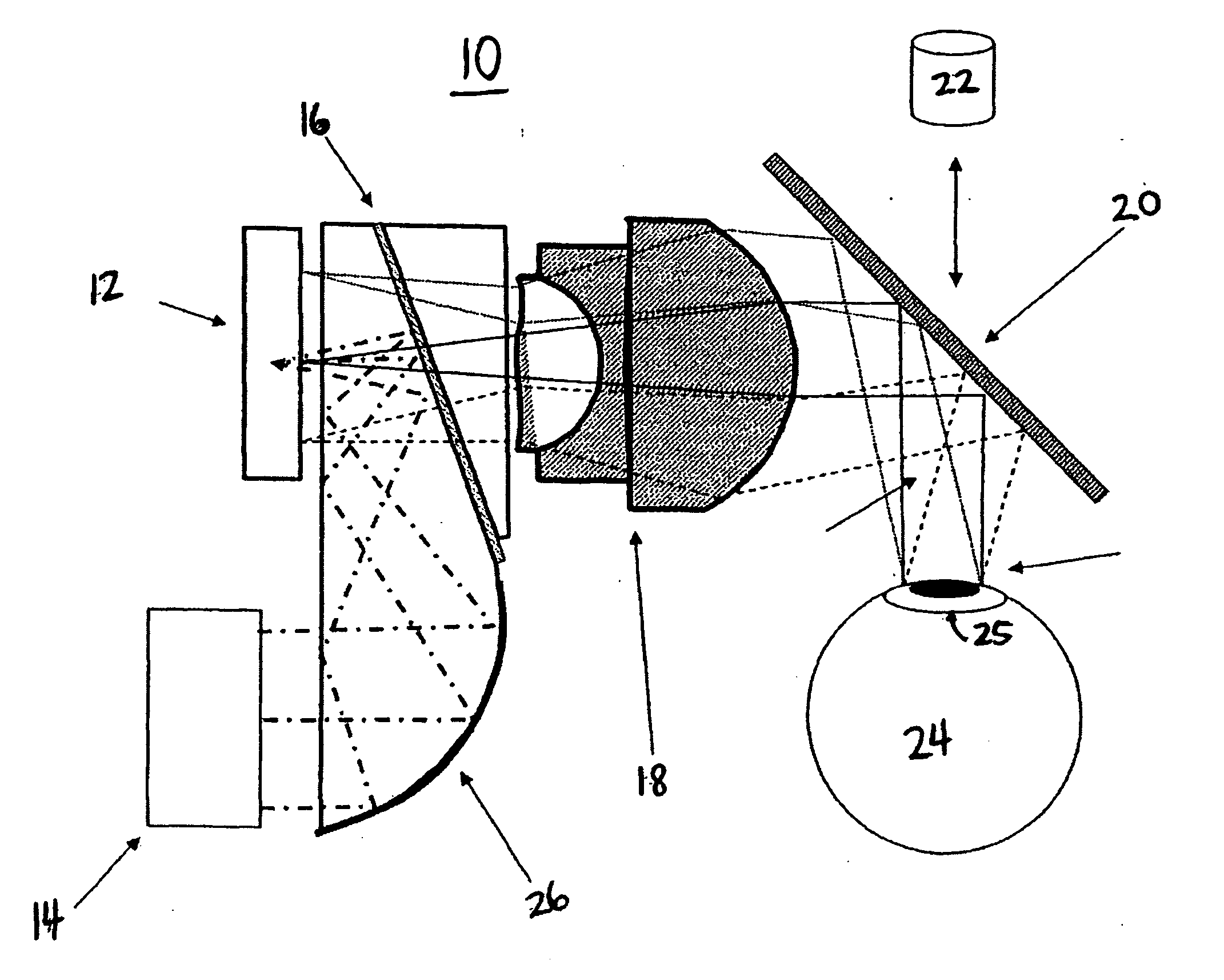
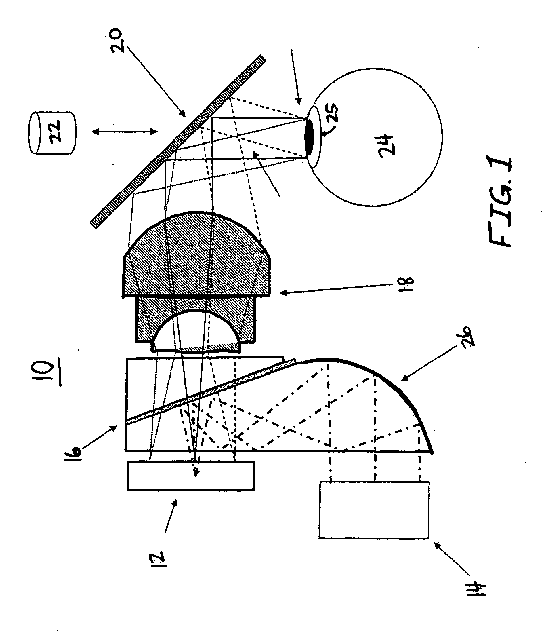
[0020] Referring now to the drawing figures, wherein like elements are denoted by like reference numbers, there is illustrated in FIG. 1 an embodiment of a wearable display system, such as a Head Mounted Display (HMD) 10, which combines a synthetic image with a contemporaneously viewable “real image” of the outside world. As shown, the HMD 10 can comprise a display engine 12 which produces linearly polarized light defining the synthetic image, a light engine 14 which produces light (typically unpolarized) to illuminate the display engine 12, a polarizing beamsplitter 16 in the path of the light produced by the light engine 14 which polarizes at least a portion of the light from the light engine 14 and reflects the polarized portion of light onto the display engine 12 (enabling the display engine 12 to produce the linearly polarized light defining the synthetic image), display optics 18 in the path of the linearly polarized light defining the synthetic image, and a wire grid polarizi...


PUM


Abstract

A wearable display system, such as a Head Mounted Display, having a display engine producing light, preferably linearly polarized light, which defines a synthetic image that is relayed to a wire grid polarizing combiner which overlays the synthetic image onto a real image of an object of the outside world, and wherein the real image is contemporaneously viewed through the wire grid polarizing combiner by the wearer of the system. The wire grid polarizing combiner can be curved in at least one axis, and preferably two axis such that optical power is added to the wire grid polarizing combiner.

Description

CROSS-REFERENCE TO RELATED APPLICATION [0001] This application claims priority to U.S. Provisional Patent Application Ser. No. 60 / 608,406, filed Sep. 8, 2004.FIELD OF THE INVENTION [0002] The invention relates to wearable display systems, such as a Head Mounted Display, and more particularly to a Head Mounted Display having wire grid polarizing combiner which combines a synthetic image with a contemporaneously viewed real image. BACKGROUND OF THE INVENTION [0003] Wearable display systems, and particularly Head Mounted Display (HMD) systems, are well known in the art. HMDs have been conceptualized and manufactured for over 40 years. The first HMD was constructed in the 1960's by Ivan Sutherland. Since Sutherland's 40 pound monochrome HMD, great strides have been made in the field. Most modern augmented-vision HMDs use three general techniques for overlaying information onto an outside real-world environment (augmenting reality or vision). The first technique combines visual data with...

Claims


Application Information

Patent Timeline
Patent Type & Authority Applications(United States)
IPC IPC(8): G02B27/01
CPCG02B5/30G02B2027/011G02B27/0172Y10S359/90
Inventor GAROUTTE, JOHNBAJORINS, DAVIDGNEHM, CHRIS
Owner CONCURRENT TECH
Why Eureka
Try Eureka