Lower and upper end plugs of an annular fuel rod

a fuel rod and annular technology, applied in the field of annular fuel rods, can solve the problems of reducing the flow rate in the inner channel, blocking the inner channel, and cooling water to mov

Inactive Publication Date: 2008-01-17
KOREA ATOMIC ENERGY RES INST +1
View PDF4 Cites 30 Cited by
  • Summary
  • Abstract
  • Description
  • Claims
  • Application Information

AI Technical Summary

Benefits of technology

[0023] Accordingly, the present invention has been established by bearing in mind the above problems occurring in a prior art, and an object of the present invention is to provide lower and upper plugs of an annular fuel rod, in which a filter for debris is installed in the inner channel main inlet of a lower end plug, thereby intercepting an inflow of debris, in which at least one inner channel auxiliary inlet with a through-hole shape is formed in the cylindrical wall of the lower end plug, thereby supplying cooling water when the debris is caught up in the debris filter to thus prevent the inner surface temperature of the fuel rod from increasing excessively and in which an upper end plug is provided with a groove in which a tool for pulling the fuel rod is located, thereby making it easy to handle the fuel rod when a nuclear fuel assembly is being assembled or disassembled.

Problems solved by technology

Meanwhile, in the case of the annular fuel rod, an external subchannel exchanges cooling water freely with the adjacent external auxiliary channels, because the inner channel makes it impossible for the cooling water to move between the channels because it is enclosed by the inner cladding tube.
Therefore, the debris floating in the cooling water is caught in the inner channel, thereby blocking the inner channel.
Further, in a case where the debris blocks the inner channel, it obstructs the flow of the cooling water to reduce the flow rate in the inner channel.
For this reason, the heat generated from the wall of the inner channel cannot be sufficiently removed, and thus the temperature of the channel wall surface increases.
Furthermore, when the temperature continues to increase, the wall surface of the inner channel is damaged which can cause accidents such as damage to the nuclear reactor.
Further, the debris filter of the lower end fitting of the nuclear fuel assembly cannot completely filter the debris, and thus the debris flowing from the lower end fitting flows into the subchannel.

Method used


Image

  • Lower and upper end plugs of an annular fuel rod
  • Lower and upper end plugs of an annular fuel rod
  • Lower and upper end plugs of an annular fuel rod

Examples


Embodiment Construction

[0051] Reference will now be made in greater detail to an exemplary embodiment of the invention, an example of which is illustrated in the accompanying drawings. Wherever possible, the same reference numbers will be used throughout the drawings and the descriptions, to refer to the same or like parts.

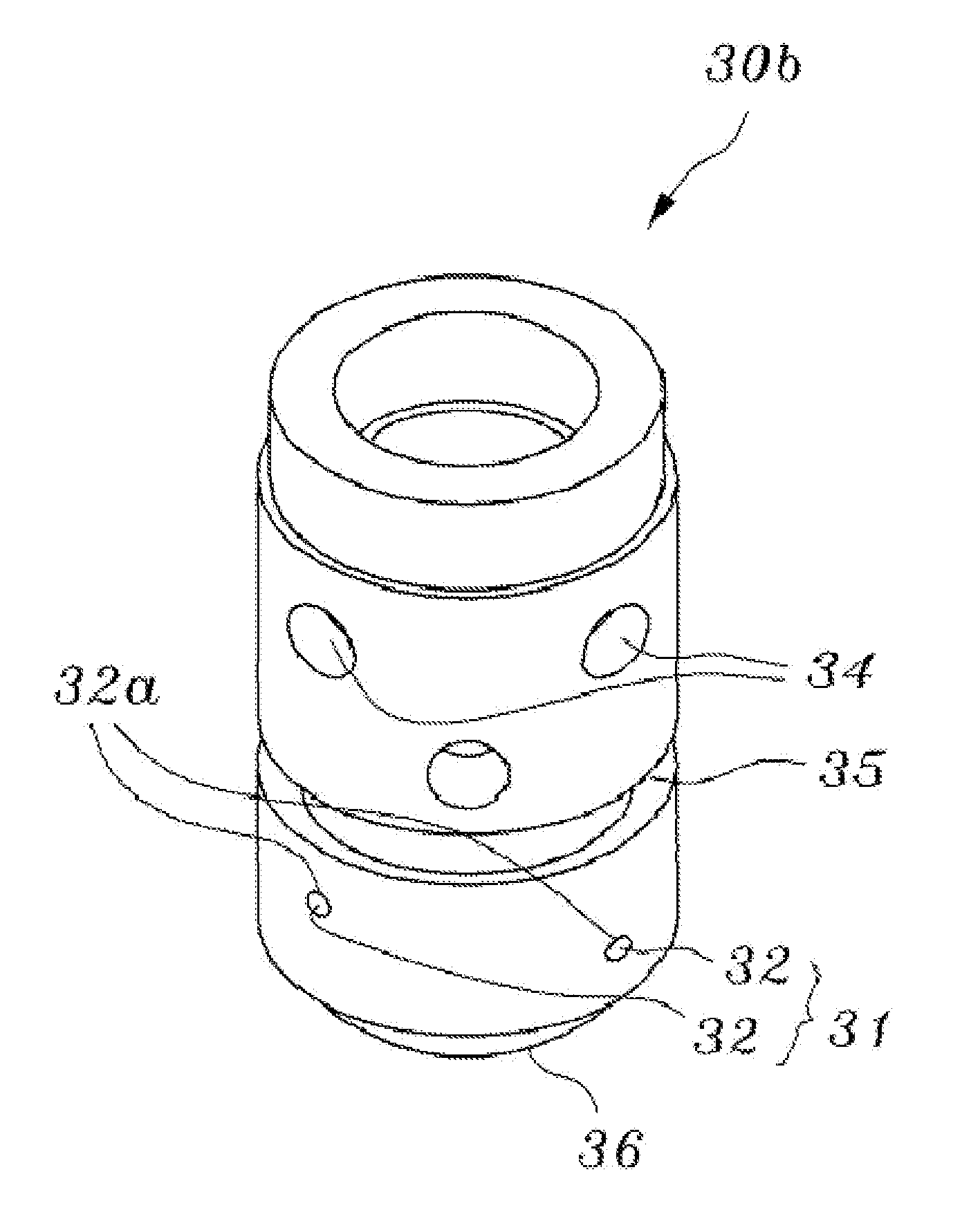
[0052]FIG. 6 is a schematic perspective view illustrating a lower end plug of the lower and upper end plugs of an annular fuel rod according to an embodiment of the present invention. FIG. 7 is a schematic transverse sectional view illustrating a lower end plug of the lower and upper end plugs of an annular fuel rod according to an embodiment of the present invention. FIG. 8 is a schematic bottom view illustrating a lower end plug of the lower and upper end plugs of an annular fuel rod according to an embodiment of the present invention. FIG. 9 is a schematic longitudinal sectional view illustrating a lower end plug of the lower and upper end plugs of an annular fuel rod according to a...


PUM


Abstract

A lower and upper end plugs of an annular fuel rod, into and out of which cooling water flows, comprises: a lower end plug including a filter for debris which has a plurality of pins intersecting each other at the proper position of an inner channel main inlet, through-holes into which the pins of the debris filter are fitted, and at least one inner channel auxiliary inlet through which the cooling water flows into a lower inner channel thereof when the inner channel main inlet is blocked by debris, and which has a through-hole shape; and an upper end plug including at least one upper handling groove and hole, into which a fuel rod handling tool is coupled, at a proper position of an inner circumference of the inner channel main outlet in a circumferential direction.

Description

BACKGROUND OF THE INVENTION [0001] 1. Field of the Invention [0002] The present invention relates to an annular fuel rod, and more particularly to a lower and upper end plug of an annular fuel rod, in which a filter for debris is installed in front of the inner channel main inlet of a lower end plug, thereby intercepting an inflow of debris in which at least one inner channel auxiliary inlet with a through-hole shape is formed in a cylindrical wall of said lower end plug, thereby supplying cooling water when the debris is caught up in the debris filter to thus prevent the inner surface temperature of a fuel rod from increasing excessively and in which the upper end plug is provided with a groove in which a tool for pulling the fuel rod is located, thereby making it easy to handle the fuel rod when a nuclear fuel assembly is being assembled or disassembled. [0003] 2. Description of the Prior Art [0004] In general, a commercial nuclear power plant is equipped with nuclear fuel assembl...

Claims


Application Information

Patent Timeline
Patent Type & Authority Applications(United States)
IPC IPC(8): G21C3/10
CPCG21C3/10G21Y2002/207Y02E30/40G21Y2002/303G21Y2004/30G21Y2002/302Y02E30/30G21C3/324G21C3/32
Inventor OH, DONG SEOKHYUN, CHUN TAEKEE, IN WANGHWAN, SHIN CHANGKYU, KIM HYUNGHO, LEE YOUNGSIK, YANG YONGGEON, BANG JENAM, SONG KEEWOO, SONG KUN
Owner KOREA ATOMIC ENERGY RES INST
Why Eureka
Try Eureka