Stress isolated pressure sensing die, sensor assembly inluding said die and methods for manufacturing said die and said assembly

a pressure sensing die and stress isolation technology, applied in the field of stress isolation pressure sensing die, can solve the problems of temperature hysteresis, compression stress locked in the rtv not returning perfectly to its original value, and the lock in die-attach stress in the rtv adhesive is reduced, so as to improve the stability of the sensor

Active Publication Date: 2008-01-24
AUXITROL
View PDF8 Cites 35 Cited by
  • Summary
  • Abstract
  • Description
  • Claims
  • Application Information

AI Technical Summary

Benefits of technology

[0031] The thinned down web absorbs some of the die-attach stress allowing only a fraction of the remaining stress to reach the middle link. Therefore, stress reduction by the flexible web and the small link combine to prevent most of the die attach stress from reaching the pressure sensing diaphragm. Sensor stability is improved significantly.
[0032] According to yet another aspect of the invention, the bottom platform comprises a second small link placed on its outer edge, and in particular on the outer edge of the rigid outer frame. First and second small links are connected to the top platform. The second—the outer—link acts as a small stress isolating link between the top and the bottom platforms. The thin web surrounding the middle vented link provides a flexible seal for the bottom platform that prevents the pressure from leaking through the vent hole in the base.

Problems solved by technology

However, the temperature variations increase and decrease the locked in die-attach stress in the RTV adhesive.
And, since RTV is not perfectly elastic, the compression stress locked in the RTV does not return perfectly to its original value after each temperature cycle involving temperature hysteresis.
This temperature hysteresis is the main source of short term instability and drift of sensor offset.
In addition, the effects of continuing bond relaxation and RTV aging are the source for long term deterioration of die-attach stresses and produce long term sensor drift.
As a result, pressure sensors employing conventional pedestals suffer from short and long term drift problems, which are exacerbated in low pressure range sensors that employ thin diaphragms.
Since their geometry is dictated by the limited thickness of silicon wafer used in MEMS sensors, this approach requires multiple upper and a lower surface channels is slots with very thin webs, which is problematical and costly to implement.
Furthermore, etching slots or channels in the silicon die around the sensing diaphragm in close proximity to the piezoresistors may create stability problems.

Method used


Image

  • Stress isolated pressure sensing die, sensor assembly inluding said die and methods for manufacturing said die and said assembly
  • Stress isolated pressure sensing die, sensor assembly inluding said die and methods for manufacturing said die and said assembly
  • Stress isolated pressure sensing die, sensor assembly inluding said die and methods for manufacturing said die and said assembly

Examples


first embodiment

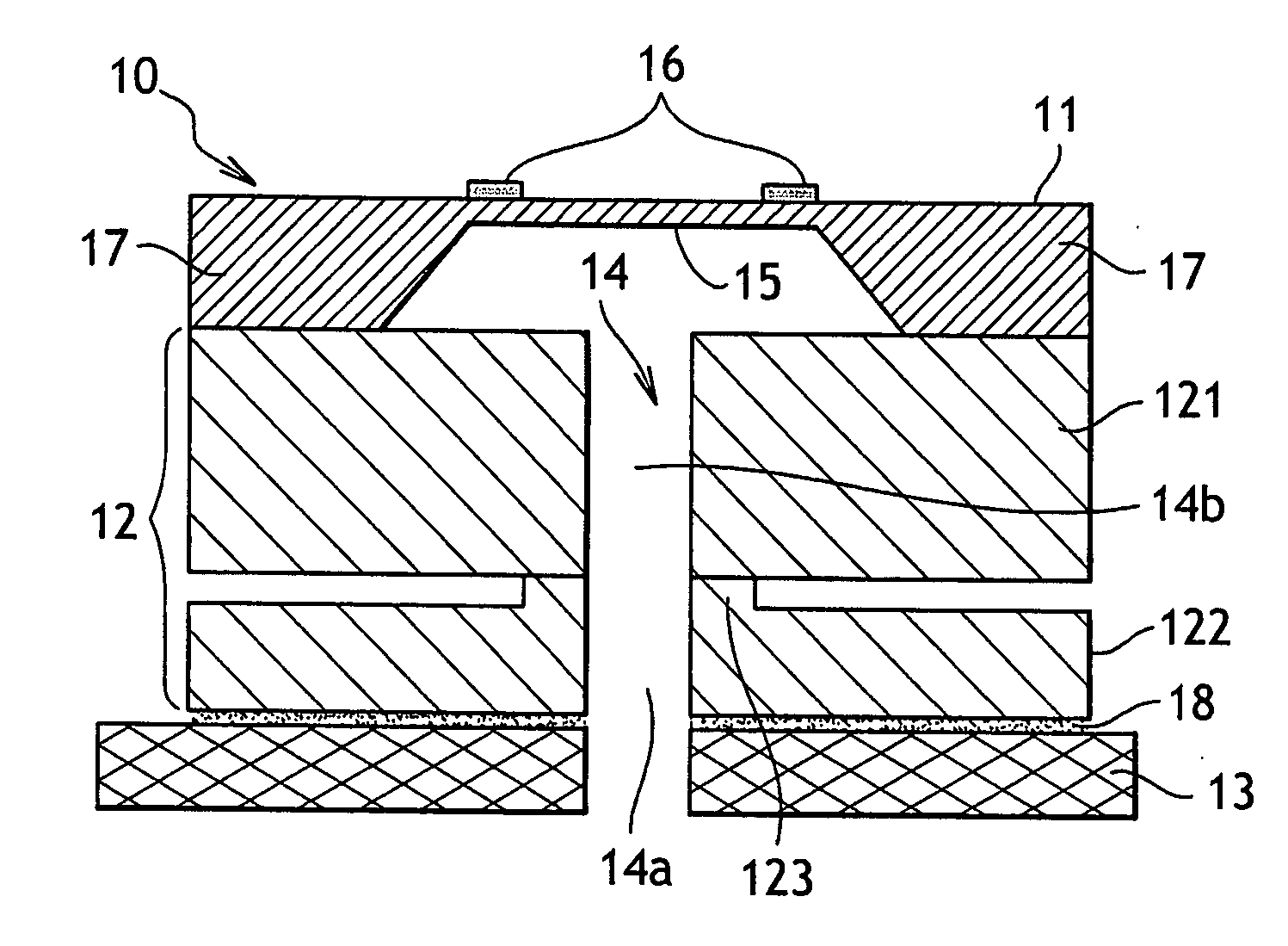
[0061]FIG. 2 is a cross-sectional view of a triple stack sensor die, with a composite pedestal 12 mounted on a base 13. Composite pedestal 12 comprises a top platform 121 and a bottom platform 122.

[0062] A diaphragm structure 11 is connected to top platform 121, for example through a bonding, such as an anodic bonding. Said diaphragm structure 11 comprises a sensing diaphragm 15 supported by rigid outer frames 17 which are bulk micro machined by chemical etching of the bottom surface of a silicon wafer. Strain gages, or piezoresistors 16 are diffused,implanted or deposited on the diaphragm 15 for sensing the stress produced in the diaphragm by applied pressure.

[0063] Top and bottom platforms 121 and 122 of the composite pedestal 12 are connected by a link 123 having a mean cross-section smaller than the cross-section of the top platform. Said small link 123 implements isolating deflectable pressure sensing diaphragm 11 mounted on the top platform of the composite pedestal from at ...

second embodiment

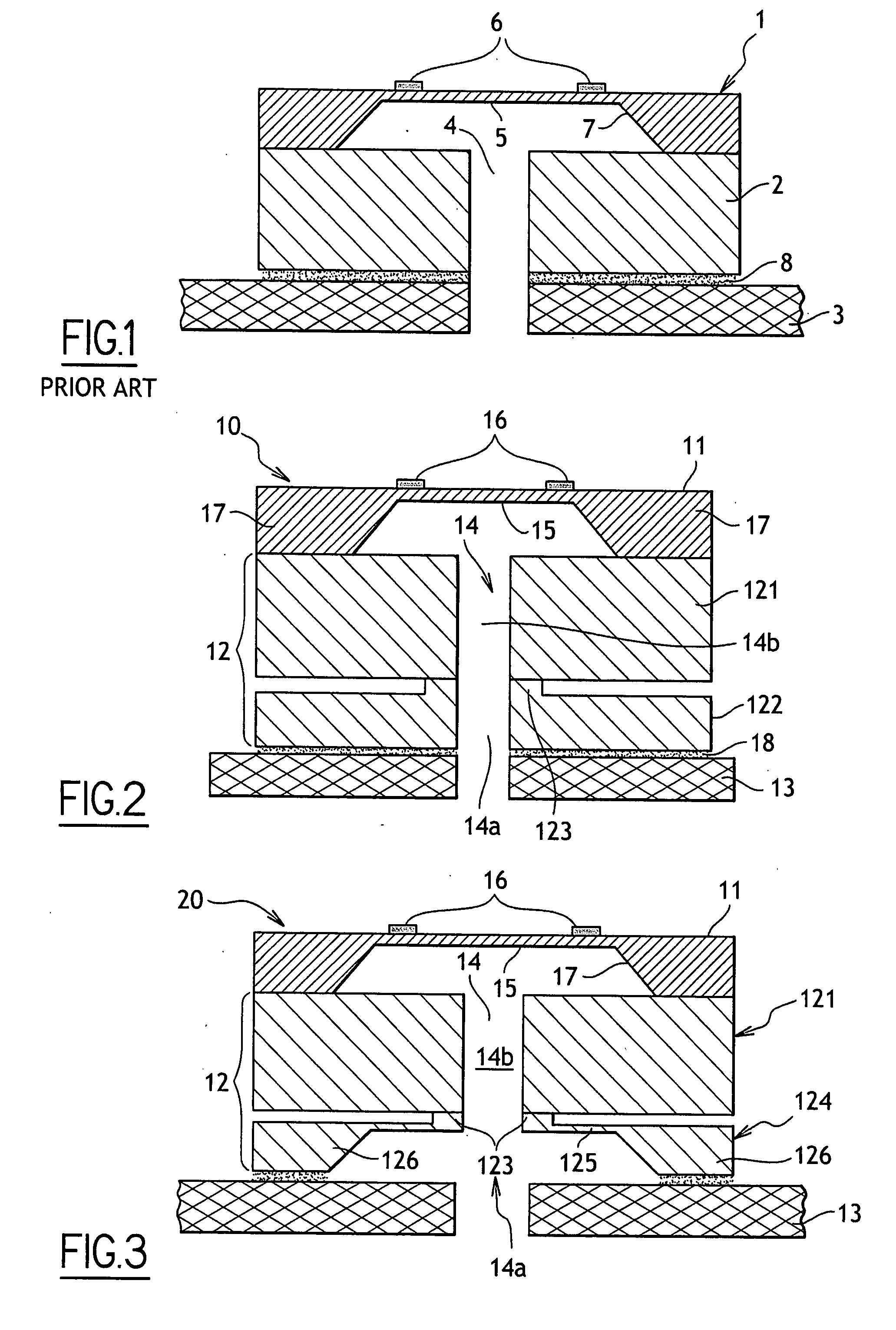
[0073]FIG. 3 illustrates a cross-sectional view of a vented version of a triple stack pressure sensing die with a flexible composite pedestal mounted on a header or substrate.

[0074] On the embodiment as represented on this drawing, bottom platform 122 of the die represented on FIG. 2 is replaced by bottom platform 124 which comprises a central bulk micro machined flexible membrane 125, supported by rigid outer frames 126, formed on a silicon wafer by chemical etching of the bottom surface of a silicon wafer. Flexible membrane 125 is thinned down so as to form a thinned-down web. In addition, small protrusions, surrounded by the thinned-down web 125, are surface machined on the top surface of the silicon wafer to realize small link 123.

[0075] The diaphragm structure 11 is bonded on the top of top platform Pyrex wafer 121 to form a triple silicon-Pyrex-silicon wafer assembly 20. The triple wafer assembly is sawed into triple stack dies 20 whereby the protrusions 123, surrounded by t...

third embodiment

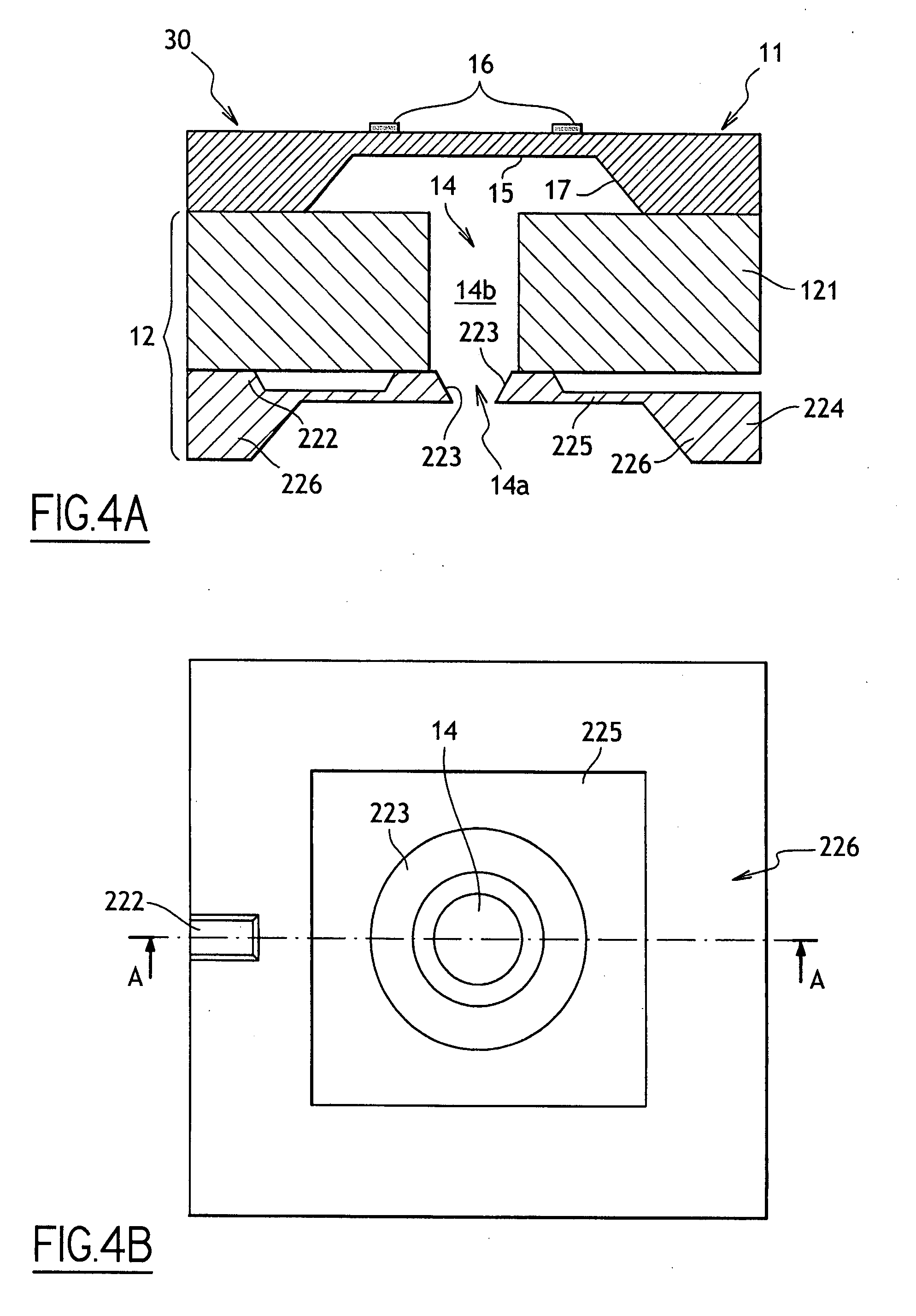
[0079]FIG. 4A illustrates a cross-sectional view of a vented version of a triple stack pressure sensing die employing a dual link composite pedestal and FIG. 4B shows the view of the vented version of a triple stack pressure sensing die employing a dual link composite die.

[0080] On this figure, the bottom platform corresponds to element 224 which comprises a flexible membrane 225, supported by a rigid outer frame 226 which is bulk micro machined by chemical etching of the bottom of a silicon wafer. In addition, two small protrusions 222 and 223 are surface machined on the top surface of the silicon wafer. Protrusion 222 is on the outer edge of rigid outer frame 226. It may be a rod or tapered shaped. Protrusion 223 is situated in the middle of flexible membrane 225. It may be square-shaped.

[0081] The diaphragm structure 11 is bonded on the top of top platform 121 to form a triple silicon-Pyrex-silicon wafer assembly 30.

[0082] The triple wafer assembly is sawed into triple stack d...


PUM

PropertyMeasurementUnit
flexibleaaaaaaaaaa
pressureaaaaaaaaaa
pressuresaaaaaaaaaa

Abstract

The invention concerns a pressure sensing die to be mounted on a base, comprising: a diaphragm structure with a deflectable pressure sensing diaphragm whose deflection is representative of the pressure and sensing elements for detecting the deflection of the sensing diaphragm; a pedestal supporting the diaphragm structure; wherein the pedestal is a composite pedestal comprising top and bottom platforms connected by at least one small link having a mean cross-section smaller than the cross-section of the top platform, said small link isolating at least some of the stresses, produced by the mounting of the pressure sensing die on the base, from said deflectable pressure sensing diaphragm.

Description

FIELD OF THE INVENTION [0001] The present invention relates to sensor assemblies. More particularly, it relates to sensor assemblies of the type comprising: [0002] a sensing die including a deflectable sensing diaphragm whose deflection is representative of the pressure and sensing elements for detecting the deflection of the diaphragm; [0003] a base for mounting the sensing die. [0004] The invention also relates to such a stress isolated pressure sensing die, as well as to methods for manufacturing said die and said assembly. BACKGROUND OF THE INVENTION [0005] One already knows dual stack sensor MEMS assemblies, wherein the sensing die comprises a Pyrex® pedestal supporting a sensing diaphragm, mounted on a metal, ceramic or plastic base. [0006] Such a dual stack pressure sensing die is illustrated on FIG. 1 with a pressure sensing structure 1 and a pedestal 2. [0007] Pressure sensing structure 1 generally consists of a bulk micro machined diaphragm 5 supported by rigid outer frame...

Claims


Application Information

Patent Timeline
Patent Type & Authority Applications(United States)
IPC IPC(8): G01L7/08B23P19/04
CPCY10T29/53174G01L19/146
Inventor BRIDA, SEBASTIANOBROSH, AMNON
Owner AUXITROL
Why Eureka
Try Eureka