Pressure balancing accumulator

Inactive Publication Date: 2008-01-24
PARKER-HANNIFIN CORP
View PDF12 Cites 7 Cited by
  • Summary
  • Abstract
  • Description
  • Claims
  • Application Information

AI Technical Summary

Benefits of technology

[0007] The present invention provides an accumulator and associated method for substantially reducing if not eliminating the bump energy event. According to one aspect of the invention, a bypass or pressure equalizing passage is provided between upper portions of a U-shape return tube for reducing the pressure difference on opposite sides of any accumulated liquid refrigerant in the bottom of the return tube upon compressor start-up. This prevents or substantially prevents the liquid “slug” from entering the suction line leading to the compressor. The reduced pressure difference also reduces the rate of “boiling” of the liquid resulting from the sudden drop of pressure at the accumulator outlet.
[0008] According to another aspect of the invention, the diameter of the U-shape return tube in the lower region of the accumulator's canister is reduced relative to the diameter of the upper portions of the return tube, thereby reducing the volume of liquid refrigerant that can accumulate in the return tube. The reduction also increases the flow velocity of the gas phase refrigerant for improving oil recirculation. The inside diameter of the bottom of the return tube can be approximately the same as a tube connecting the upper ends of the return tube. In addition, the combined cross-sectional areas of the connecting tube and lower region of the U-tube can be approximately equal the flow area of the upper ends of the return tube.

Problems solved by technology

Although this design does reduce the bump energy, it has difficulty returning a sufficient amount of oil back to the compressor.
Another attempt disclosed in U.S. Pat. No. 6,389,842 provides adequate oil recirculation, but does not adequately eliminate the bump energy event.

Method used


Image

  • Pressure balancing accumulator
  • Pressure balancing accumulator
  • Pressure balancing accumulator

Examples


Embodiment Construction

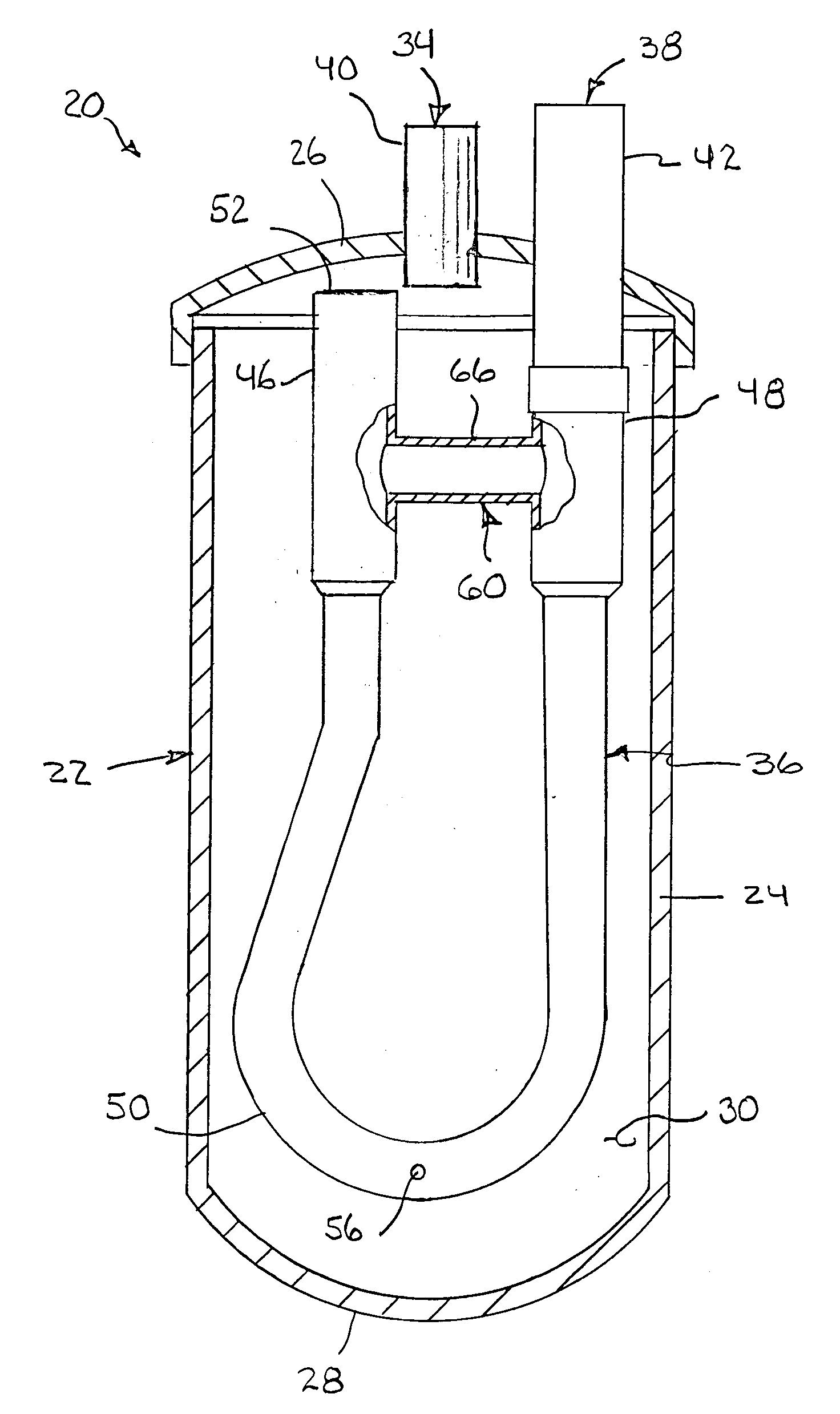
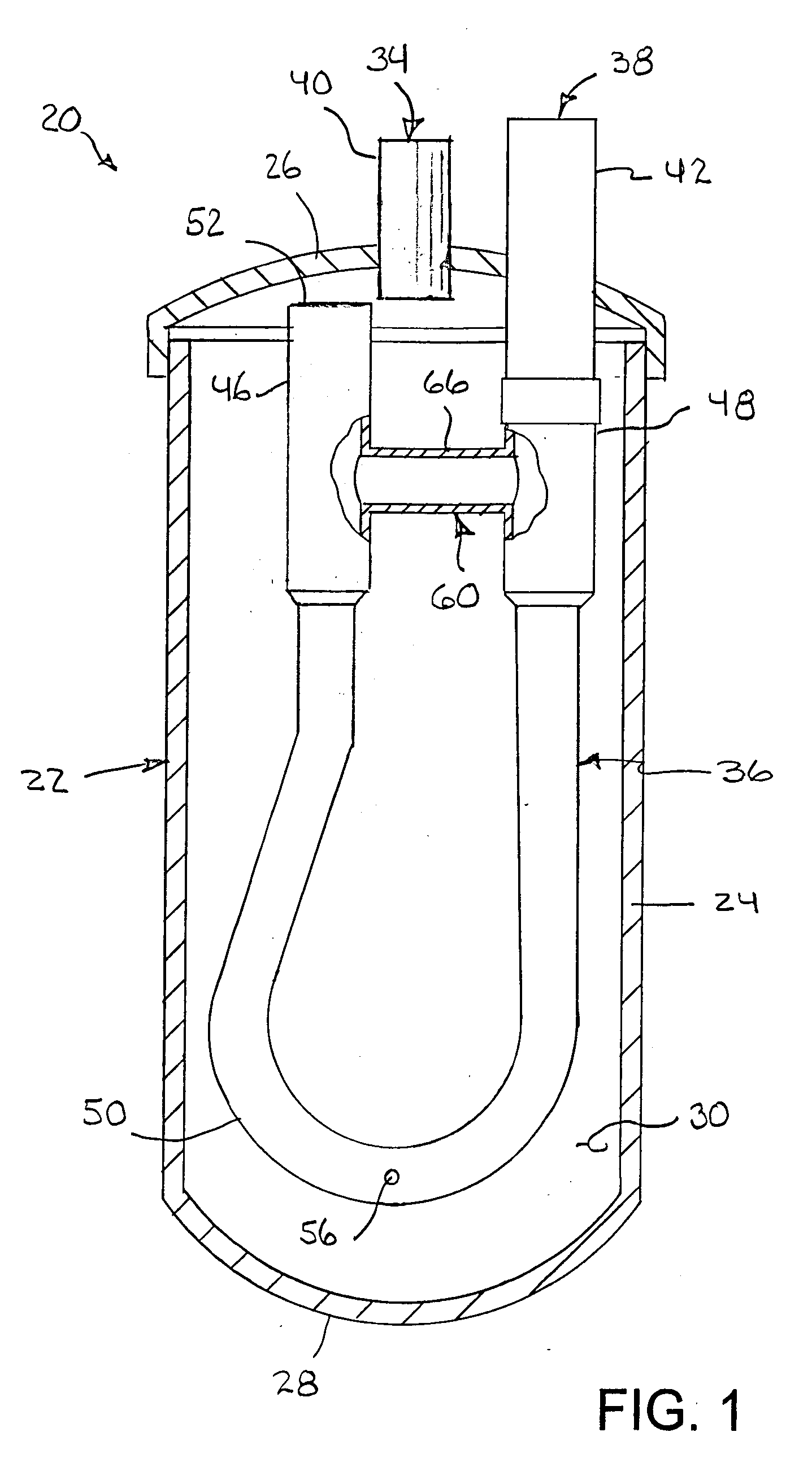
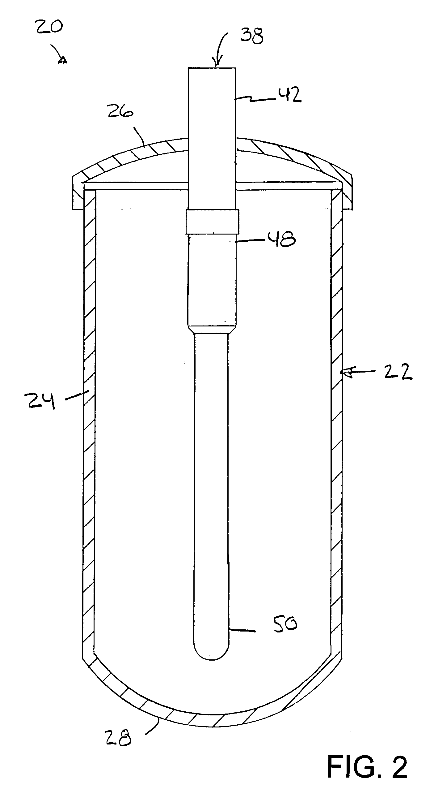
[0027] Referring now to the drawings in detail and initially to FIGS. 1 and 2, an exemplary accumulator according to the principles of the present invention is illustrated generally at 20. The accumulator includes an outer canister, housing or other container 22. The container 22 has a tubular sidewall or shell 24, an upper end wall 26 and a lower end wall 28. The shell may be cylindrical, and the sidewall and lower end wall may be formed together in one piece using common forming techniques such as impacting or extruding a sheet of metal or injection molding plastic. The upper end wall 26 may be formed separately as a cap or cover that is joined by any suitable means in a fluid-tight manner to the upper end of the shell 24. The upper end wall 26, lower end wall 28 and cylindrical sidewall 24 define an internal chamber indicated generally by reference number 30. As shown, the end walls may be convexly or dome shaped as is conventional.

[0028] The illustrated accumulator 20 is partic...


PUM


Abstract

An accumulator and associated method substantially reduces if not eliminates a bump energy event associated with the use of a U-tube. A bypass or pressure equalizing passage is provided between upper portions of a U-shape return tube for reducing the pressure difference on opposite sides of any accumulated liquid refrigerant in the bottom of the U-tube upon compressor start-up. This prevents or substantially prevents the liquid “slug” from entering the suction line leading to the compressor. The diameter of the U-tube in the lower region of the accumulator's canister is reduced relative to the diameter of the upper portions of the return tube, thereby reducing the volume of liquid refrigerant that can accumulate in the return tube. The reduction also increases the flow velocity of the gas phase refrigerant for improving oil recirculation.

Description

RELATED APPLICATIONS [0001] This application claims the benefit of U.S. Provisional Application No. 60 / 793,213 filed Apr. 19, 2006 and 60 / 802,441 filed May 22, 2006, both of which are hereby incorporated by reference.FIELD OF THE INVENTION [0002] The herein described invention relates generally to accumulators for air conditioner and other refrigerant systems and the like, including in particular accumulators using U-shaped or J-shaped tubes and particular. BACKGROUND OF THE INVENTION [0003] Conventional refrigeration systems include a compressor, a condenser, an expansion device, and an evaporator. Refrigerant is circulated through the system to produce cooling. Energy is provided to the system by the compressor which serves to create a source of high pressure gas refrigerant that is allowed to pass through the condenser. The refrigerant dissipates heat in the condenser and changes state to a high pressure liquid. The refrigerant then passes through the expansion device and into th...

Claims


Application Information

Patent Timeline
IPC IPC(8): F25B5/00
CPCF25B43/006F25B2500/28F25B2500/01
Inventor LOCKE, MARCOS A.STEINMANN, GENE E.MILLER, JOHN W.
Owner PARKER-HANNIFIN CORP
Why Eureka
Try Eureka