Thermal type flow sensor

Active Publication Date: 2008-01-24
HITACHI ASTEMO LTD
View PDF17 Cites 22 Cited by
  • Summary
  • Abstract
  • Description
  • Claims
  • Application Information

AI Technical Summary

Benefits of technology

[0012]The present invention has been accomplished with a view to overcome the aforementioned problems of the prior art and therefore, an object of the present invention is to provide a thermal type flow sensor which is capable of reducing the measurement error that may be caused due to the

Problems solved by technology

Since the thermal type flow sensor of semiconductor type is formed of a plate-like sensor element, the accuracy of measurement will be greatly affected when any disturbance is caused to generate in the flow of fluid around the sensor element.
Therefore, the problem is how to create the structure that cannot be badly affected by the disturbance in flow of fluid as described above.
Depending on the manufacturing conditions however, the surface of sensor element may be protruded or depressed from the surface of the inner wall of measuring passage (forming a step portion), thus creating non-uniform surface.
As a result, true fluid flow may be caused to differ from the fluid flow around the sensor element, thus generating an error of measurement.
However, in order to secure a sufficient isolation distance from the edge portion of sensor element, the surface area of sensor element is required to be increased, inevitably leading to an increase in manufacturi

Method used


Image

  • Thermal type flow sensor
  • Thermal type flow sensor
  • Thermal type flow sensor

Examples


Example

First Embodiment

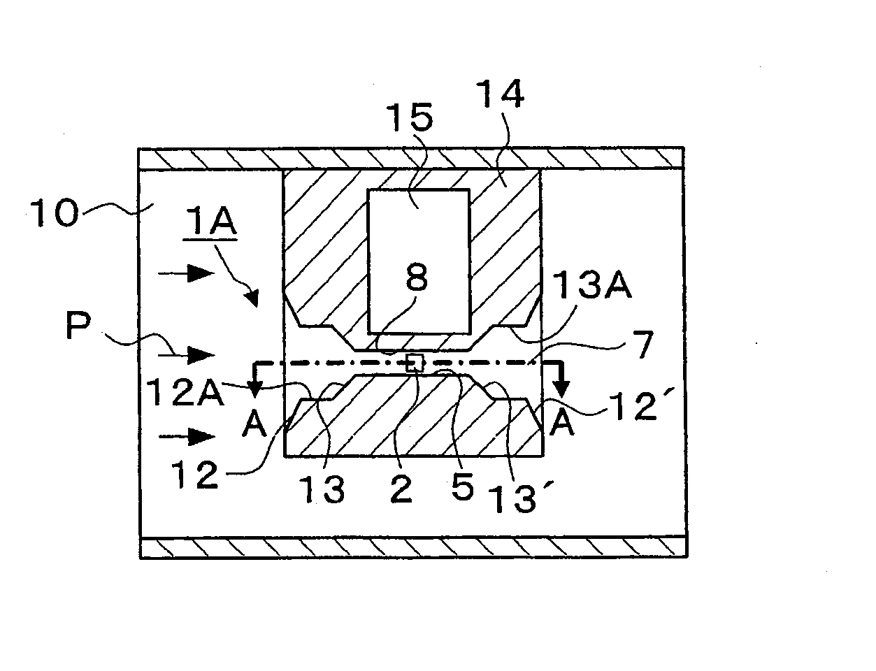
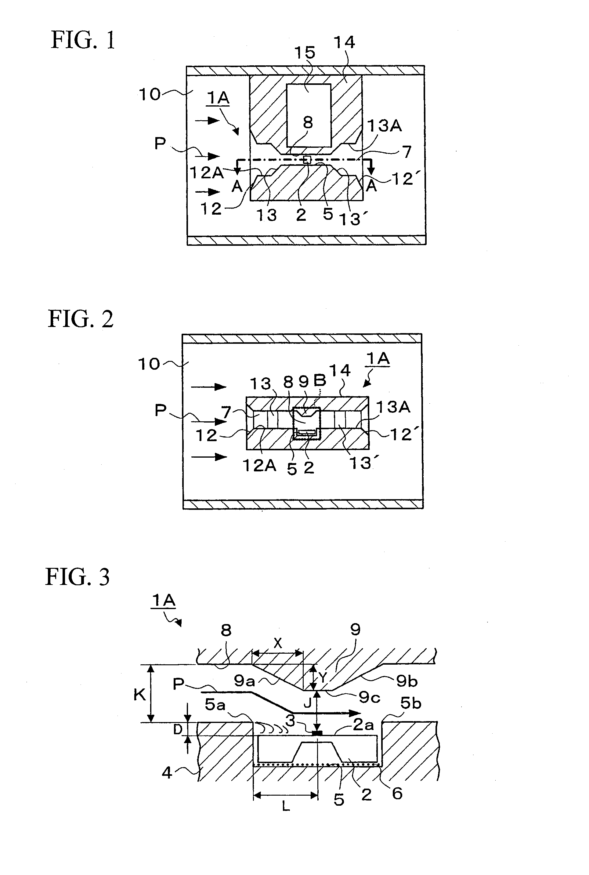
[0047]FIG. 1 is a cross-sectional view illustrating a state wherein the thermal type flow sensor 1A according to a first embodiment of the present invention is installed in a main passage 10 (the air intake passage of vehicle-mounting internal combustion engine); FIG. 2 is an enlarged cross-sectional view taken along the line A-A of FIG. 1; and FIG. 3 is an enlarged view of the region “B” of FIG. 2.

[0048]The thermal type flow sensor 1A shown herein is provided therein with a sensor element 2 equipped with an exothermic resistor 3 which is formed on a substrate for detecting the flow rate of the fluid passing through a main passage 10, and also provided therein with a circuit board 15 on which electronic circuit components for detecting flow rate and a wiring pattern are formed. Further, the thermal type flow sensor 1A is further provided with a sensor housing 14 in which a sub-passage 7 having a rectangular cross-section is formed. This sensor housing 14 is mounted i...

Example

Second Embodiment

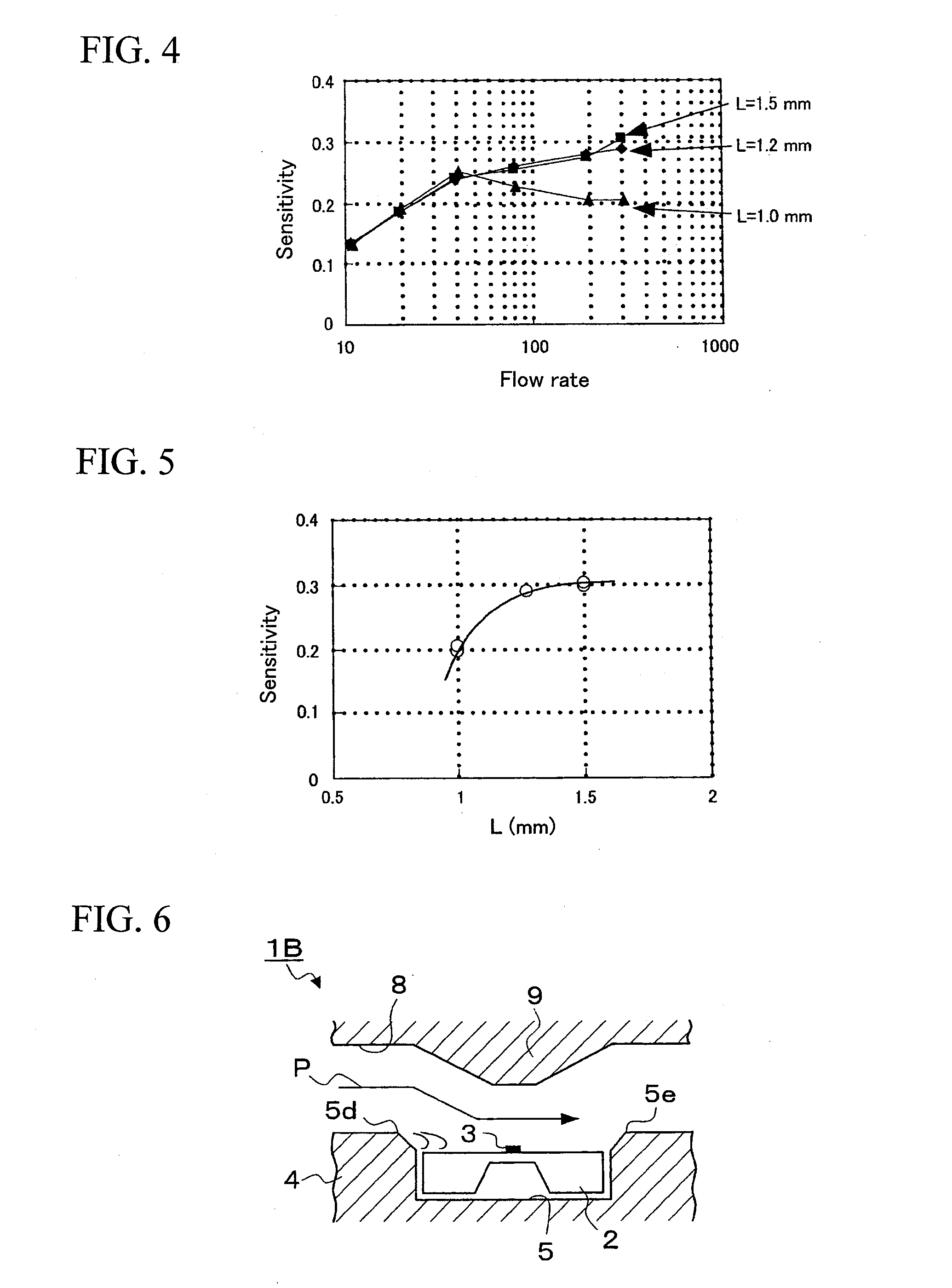
[0061]FIG. 6 shows a main portion of the thermal type flow sensor 1B according to a second embodiment of the present invention. In the thermal type flow sensor 1B of this embodiment, the components which correspond to those of the thermal type flow sensor 1A according to the first embodiment will be identified by the common symbols and differences in structure between these embodiments will be mainly explained in the following description. In this embodiment, the upper corner portion 5d on the upstream side of the recessed portion 5 formed in the base portion 4 as well as the upper corner portion 5e on the downstream side thereof is formed into a slanted surface (chamfered). Namely, the peeling to be generated due to the provision of the step portion would become larger as the configuration of passage is sharply changed. Therefore, the corner portions 5d and 5e of upper edges of the upstream and downstream sides of the recessed portion 5 are formed into a slanted su...

Example

Third Embodiment

[0062]FIG. 7 shows a main portion of the thermal type flow sensor 1C according to a third embodiment of the present invention. In the thermal type flow sensor 1C of this embodiment, the components which correspond to those of the thermal type flow sensor 1A according to the first embodiment will be identified by the common symbols and differences in structure between these embodiments will be mainly explained in the following description. In this embodiment, the exothermic resistor 3 is positioned so as to off-set it from the center of the sensor element 2 toward the downstream side. Namely, when the distance between the upstream side upper edge 5a of the recessed portion 5 and the exothermic resistor 3 (the center thereof) is represented by “L1”, and when the distance between the exothermic resistor 3 and the downstream side upper edge 5b of the recessed portion 5 is represented by “L2”, they should be regulated to satisfy the expression of: L1>L2. In this constrict...


PUM


Abstract

A thermal type flow sensor includes a base portion provided along the direction of a fluid flowing through a main passage, and a sensor element mounted on the base portion and having an exothermic resistor formed on a substrate for detecting the fluid flow rate. The base portion has a rectangular recessed portion in which the sensor element fixed so that the surface of the detecting portion of the sensor element is positioned lower than an upper edge of the recessed portion. A wall portion of the measuring passage facing the sensor element is constricted. The exothermic resistor is disposed along the fluid passage and spaced away from the upstream side upper edge of the recessed portion and cannot be substantially affected by a fluid flow disturbance due to a step portion formed between the upper edge of the recessed portion and the detecting portion surface.

Description

BACKGROUND OF THE INVENTION[0001]The present invention relates to a thermal type flow sensor equipped with a sensor element having an exothermic resistor formed on a substrate as a detecting member for detecting the flow rate of a fluid such as air passing through an air intake passage of vehicle-mounting internal combustion engine. In particular, the present invention relates to a thermal type flow sensor which is designed to exhibit improved accuracy in the measurement of flow rate.[0002]As for the flow sensor for detecting the intake air flow of an internal combustion engine to be mounted on a vehicle, a thermal type air flow sensor which is capable of directly measuring the mass flow rate is mainly employed.[0003]In recent years, there has been proposed an idea to manufacture the sensor element of thermal type flow sensor on a semiconductor substrate such as a silicon substrate by making use of micromachine techniques. In the thermal type flow sensor of this semiconductor type, ...

Claims


Application Information

Patent Timeline
IPC IPC(8): G01F1/68G01F1/69
CPCG01F1/6845G01F1/6842
Inventor NAKANO, HIROSHIYAMADA, MASAMICHIMATSUMOTO, MASAHIROWATANABE, IZUMI
Owner HITACHI ASTEMO LTD
Why Eureka
Try Eureka