
Heat exchanger and ventilator having the same

a heat exchanger and ventilator technology, applied in the field of heat exchangers, can solve the problems of corner member loosening from the heat exchanger body, air leakage, and enormous amount of wasted electric power for air-conditioning in the indoor space, and achieve the effect of improving the structur

Active Publication Date: 2008-01-24
SAMSUNG ELECTRONICS CO LTD
View PDF13 Cites 48 Cited by
  • Summary
  • Abstract
  • Description
  • Claims
  • Application Information

AI Technical Summary

Benefits of technology

[0011]The present general inventive concept provides a heat exchanger usable with a ventilator, the heat exchanger having an improved structure so that air passing through the heat exchanger may be prevented from leaking.
[0012]The present general inventive concept provides a heat exchanger usable with a ventilator, the heat exchanger being structured so that corners of the heat exchanger may be easily mounted to an inside of the ventilator without interfering with structures in the ventilator.
[0020]The corner guides may prevent air passing through the first and second passages from being mixed.

Problems solved by technology

Therefore, ventilating without any filtering process causes much heat loss in the indoor space and may cause an enormous amount of wasted electric power for air-conditioning of the indoor space.
The gap causes air leakage.
However, in the conventional heat exchanger the corner member becomes loose from the heat exchanger body because silicon is applied between the corner member and the heat exchanger body.
Further, if silicon is not applied uniformly, there still may be air leakage through the gap between the corner member and the heat exchanger body.
Such loosening of the corner member from the heat exchanger body causes a difficulty in mounting the heat exchanger to the ventilator.
If the corner member becomes loose from the heat exchanger body, the corner member and the guide rail interfere with each other and cause a difficulty in mounting the heat exchanger to the ventilator.
Further, in the disclosed conventional heat exchanger, the metal plates disposed at the opposite ends of the heat exchanger and the corner member are secured to the heat exchanger by screw, so that the heat-exchanging sheets and the spacers may be damaged by the inserted screw and possibly cause air leakage.

Method used


Image

  • Heat exchanger and ventilator having the same
  • Heat exchanger and ventilator having the same
  • Heat exchanger and ventilator having the same

Examples


Embodiment Construction

[0035]Reference will now be made in detail to the embodiments of the present general inventive concept, examples of which are illustrated in the accompanying drawings, wherein like reference numerals refer to the like elements throughout the drawings. The embodiments are described below to explain the present general inventive concept, by referring to the figures.

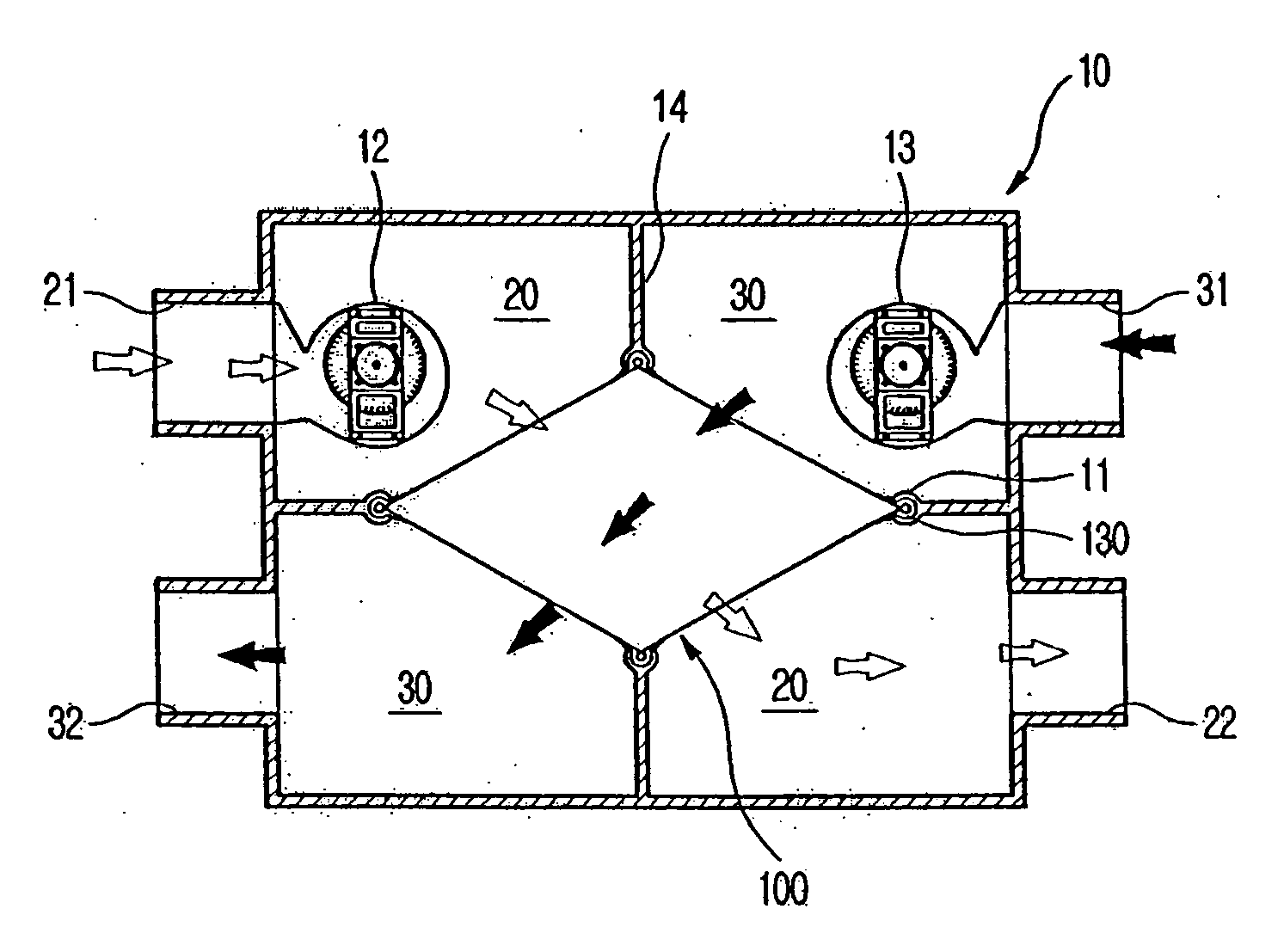
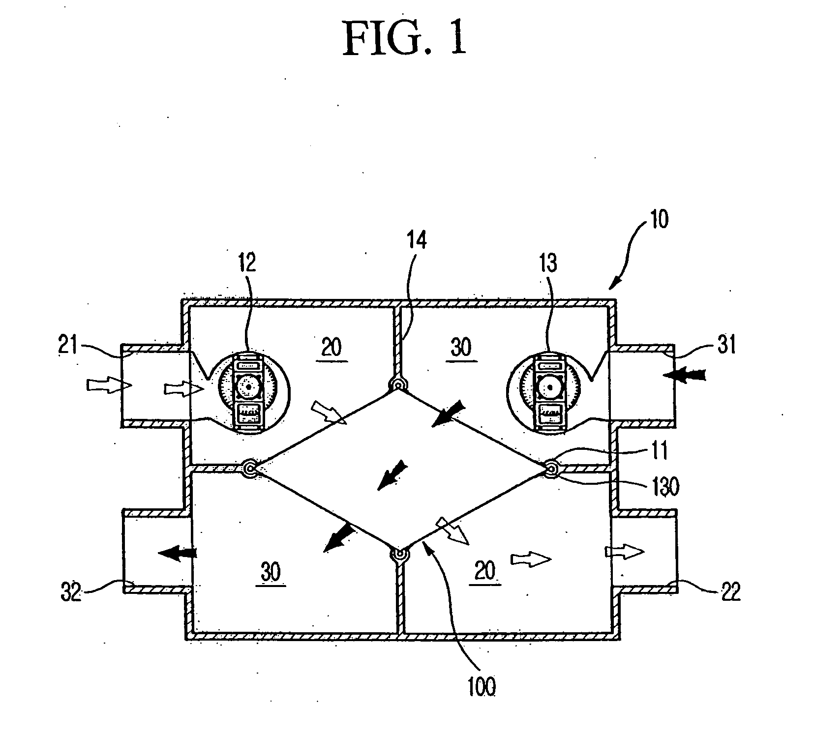
[0036]FIG. 1 illustrates a ventilator according to an embodiment of the present general inventive concept.

[0037]As illustrated in FIG. 1, the ventilator includes a body 10 provided with an intake passage 20 through which outdoor air is sucked indoors and an exhaust passage 30 through which indoor air is discharged outdoors. The interior of the body 10 is separated into the intake passage 20 and the exhaust passage 30. A plurality of partitions 14 may be included in the body 10 to separate the intake passage 20 from the exhaust passage 30. The intake passage 20 and the exhaust passage 30 are formed to cross in a diagonal dir...


PUM


Abstract

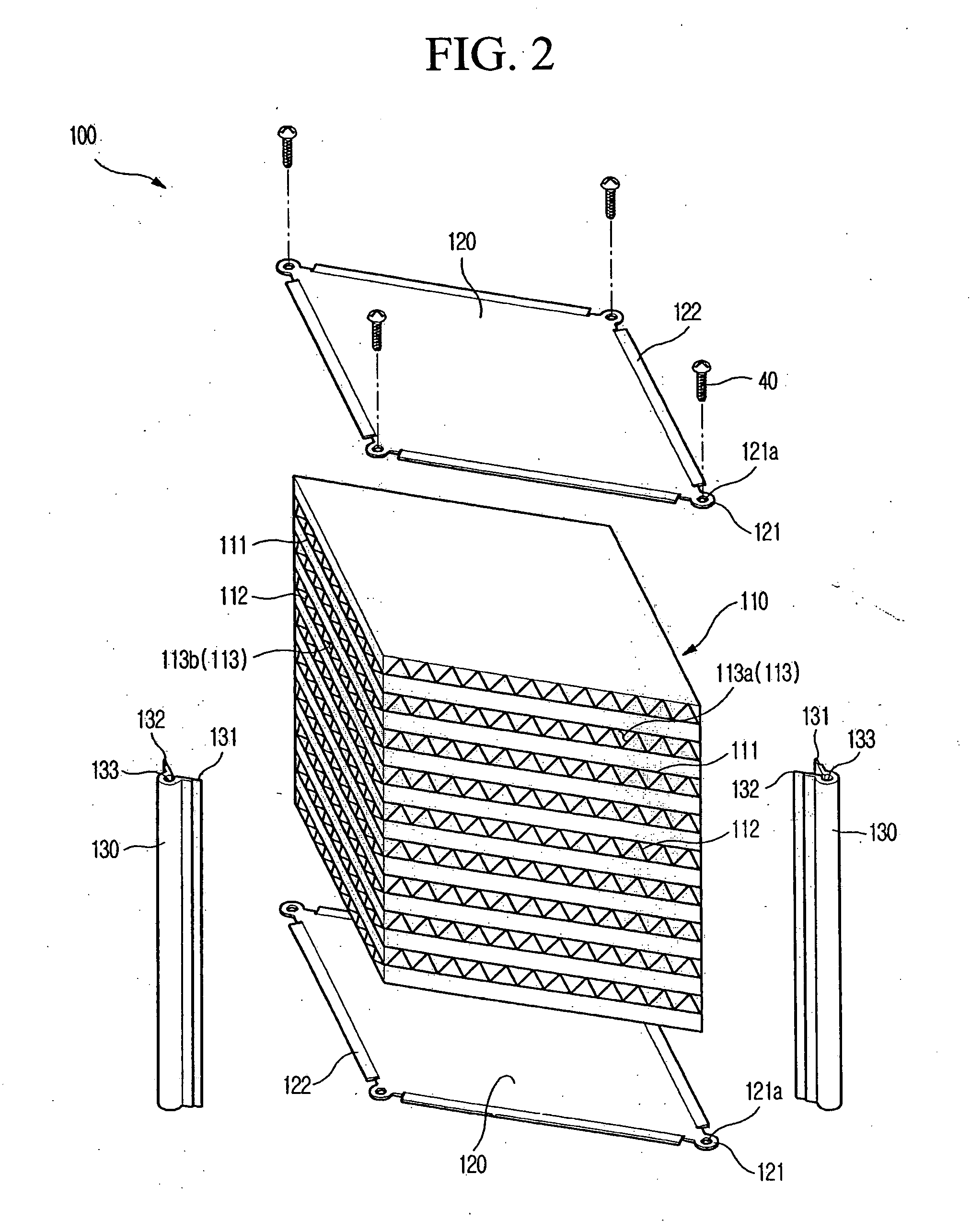
A heat exchanger usable with a ventilator, the heat exchanger having an improved structure so that air passing through the heat exchanger may be prevented from leaking. The heat exchanger of the general inventive concept includes a heat-exchanging element having a plurality of liners stacked in a uniformly spaced state and a plurality of spacers disposed between the liners to define air passages, and corner guides respectively coupled to corners of the heat-exchanging element. Each of the corner guides includes a guide channel forming a space to receive the corner of the heat-exchanging element so that the corner guides securely come into close contact with the heat-exchanging element, and to minimize a loosening of the corner guide due to an adhesive applied between the heat-exchanging element and the corner guide.

Description

CROSS-REFERENCE TO RELATED APPLICATIONS[0001]This application claims priority under 35 U.S.C. §119(a) from Korean Patent Application No. 2006-67029 filed with the Korea Industrial Property Office on Jul. 18, 2006, the disclosure of which is incorporated herein in its entirety by reference.BACKGROUND OF THE INVENTION[0002]1. Field of the Invention[0003]The present general inventive concept relates to a heat exchanger that is applicable to a ventilator, and more particularly, to a heat exchanger that is able to minimize leakage of air from corners therein.[0004]2. Description of the Related Art[0005]Generally, a ventilator expels indoor air outdoors and sucks in outdoor air indoors to ventilate an indoor space. In ventilating the indoor space, warm or cold indoor air must be discharged outdoors and warm or cold outdoor air must be introduced indoors. Therefore, ventilating without any filtering process causes much heat loss in the indoor space and may cause an enormous amount of waste...

Claims


Application Information

Patent Timeline
IPC IPC(8): F28F13/12
CPCF24F12/006F28D9/0062Y02B30/16Y02B30/563F28D9/00F28F9/001Y02B30/56F24F7/08F28F3/08Y02B30/00
Inventor KWON, YOUNG-CHULKIM, SUNG WOOCHU, EUY SUNGKIM, JEE YONG
Owner SAMSUNG ELECTRONICS CO LTD
Learn More