
System, method and process of recovering oil from used automobile tires

a technology for automobile tires and oil recovery, applied in the direction of lighting and heating equipment, separation processes, sustainable manufacturing/processing, etc., can solve problems such as not being difficult to achiev

Inactive Publication Date: 2008-01-24
THOMPSON DAVID BRENT
View PDF26 Cites 14 Cited by
  • Summary
  • Abstract
  • Description
  • Claims
  • Application Information

AI Technical Summary

Benefits of technology

[0028] The gas stream which exits the condenser still contains hydrocarbons, and this gas is captured and compressed and may be utilized as an energy source. One use of this gas is to provide heat to the pyrolysis chamber for the processing of more bundles of tire.
[0029] The purpose of the foregoing Abstract is to enable the public, and especially the scientists, engineers, and practit

Problems solved by technology

This is not difficult to attain, because the supply of automobile or vehicle tires is very large at present.

Method used


Image

  • System, method and process of recovering oil from used automobile tires
  • System, method and process of recovering oil from used automobile tires
  • System, method and process of recovering oil from used automobile tires

Examples


second embodiment

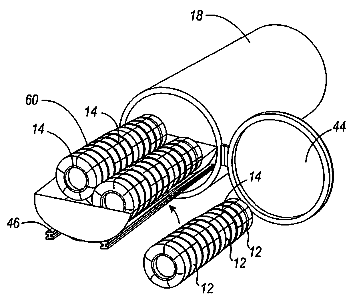
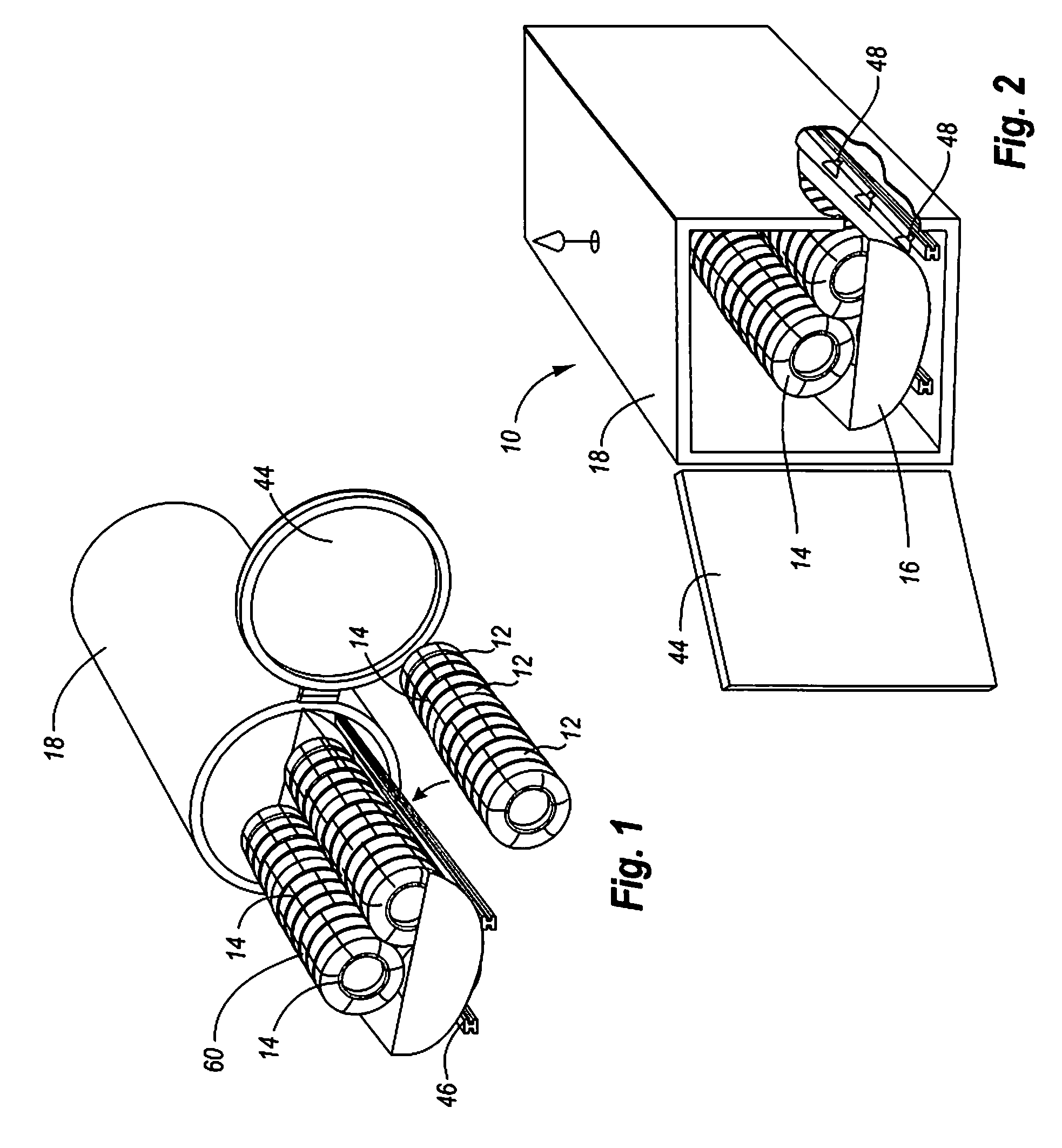
[0041] Referring to FIGS. 1-2, the present invention is shown, being a system, method and / or process 10 (hereinafter “method”) starting with a supply of used automobile tires as a fuel source. These automobile tires 12 are aligned together so that their center (wheel hub hole) passageways align, thereby forming a generally cylindrical shaped structure (bundle) 14 comprised of tires. This cylindrical structure 14 is held together, preferably through use of a plurality of wires or metal straps. Optionally, the cylinders of tires could be first compressed axially before the wires are applied. By compressing the tire cylinders, heat will be distributed better. It has been found that whole tires are preferred over shredded tires because less heat transfer is obtained if the tires are first shredded. However, baled, chopped and / or shredded tires (or any other source of high durometer / vulcanized rubber) may be used, with modifications made to the system suitable for each form of rubber.

[00...

first embodiment

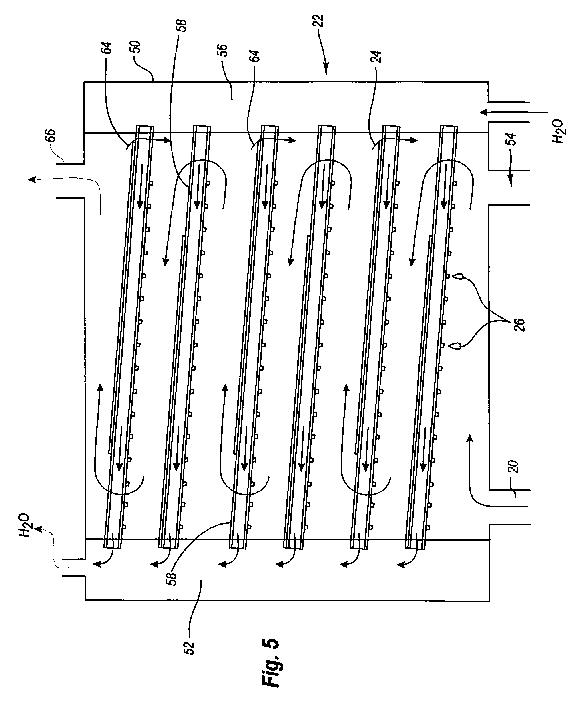
[0055] In plates (FIG. 6) the plates 30 have a top side and a bottom side, with a plurality of condensation pipes 34 attached to or located adjacent to the bottom side of the plates. The preferred plates comprise a sheet 32 (preferably of sheet metal) to which the condensation pipes 34 are welded. The preferred pipes are dark iron pipes, stainless steel, copper pipes, etc. The preferred pitch or slope of the plates is 5-15°. A plurality of protrusions / knobs / ridges / projections / drip points / dimples / etc. (“protrusions”) 35 preferably extend off the lowermost portion of the condensation pipes. These protrusions increase the surface area of the pipes and provide a location for oil to condense upon. In the preferred embodiment, these protrusions are located one-inch apart.

[0056] In a second embodiment of plate (FIG. 7), the plates 36 comprise a top plate 38, a bottom plate, and a pair of side plates forming a generally elongated rectangular tube 40 with an open first end and an open second...


PUM


Abstract

The invention is an apparatus and method for recovery of energy and by-products from automobile and truck tires. The tires are heated in an oxygen poor environment, and the off gases are condensed to recover a liquid oil product and compressible natural gas. The tires are reduces to ash and steel, both of which can be feed streams for other processes. The apparatus includes a condenser with cooled plates, and oil recovery structures.

Description

CROSS-REFERENCE TO RELATED APPLICATIONS [0001] This application claims the priority date of the provisional application entitled SYSTEM, METHOD AND PROCESS OF RECOVERING OIL FROM USED AUTOMOBILE TIRES filed by David Brent Thompson on Jun. 12, 2006 with application Ser. No. 60 / 804,508.FIELD OF THE INVENTION [0002] The present invention generally relates to an apparatus, system and method for recovering energy from automobile tires, and more particularly to an apparatus, system, and method for using pyrolysis for recovering oil and gas from automobile tires, leaving only carbon ash and steel. BACKGROUND OF THE INVENTION [0003] There are millions of cars and trucks on the roads, with millions of vehicles added each year. This results in tens of millions of tires being used and discarded each year. Disposing of these tires has proven problematic. With space in landfills becoming more and more scarce, it is not economical to dispose of automobile tires in landfills. Dumping tires in the ...

Claims


Application Information

Patent Timeline
IPC IPC(8): C10B57/04
CPCC10B7/14C10B47/12C10B53/07C10G2300/1003C10J3/66C10J2300/0946F28B1/02C10G1/10Y02P20/143Y02P20/10C10K1/04
Inventor THOMPSON, DAVID BRENT
Owner THOMPSON DAVID BRENT
Learn More