Electric circuit and test apparatus

a test apparatus and circuit technology, applied in the direction of generating/distributing signals, instruments, pulse techniques, etc., can solve the problem that the test apparatus cannot switch the output signals with high precision

Inactive Publication Date: 2008-01-24
ADVANTEST CORP
View PDF4 Cites 15 Cited by
  • Summary
  • Abstract
  • Description
  • Claims
  • Application Information

AI Technical Summary

Benefits of technology

[0009]To solve the above problem, according to the first aspect of the present invention, there is provided an electric circuit including a function for outputting a timing signal with a phase according to a predetermined system timing and a function for outputting a recovered clock synchronized with a given periodic signal. The electric circuit includes: a counter delay circuit that delays a given reference signal by a delay amount according to the system timing, which is an integral multiple of a period of a given clock signal and outputs the delayed reference signal; a PLL section that generates an oscillation signal synchronized with the reference signal delayed by the counter delay circuit, and delays the oscillation signal by an offset delay amount according to the system timing to output the delayed oscillation signal when outputting the timing signal and changes a delay amount for the oscillation signal in a preset tracking range using the offset delay amount as a standard to output the oscillation signal in synchronization with the periodic signal when outputting the recovered clock; a delay amount separating section that separates a coarse component of an integral multiple of a period of the clock signal and a fine component less than the period of the clock signal from the delay amount by which the reference signal should be delayed in accordance with the system timing; a difference computing section that computes a difference between the size of the tracking range in a negative direction and the size of the fine component if the tracking range in the negative direction is larger than the fine component; and a delay setting section that sets a value obtained by subtracting an adjusted delay amount, which is not less than the difference computed from the difference computing section and is an integral multiple of the period of the clock signal, from the coarse component as the delay amount of the counter delay circuit and sets a value obtained by adding the adjusted delay amount to the fine component as the offset delay amount of the PLL section, if the tracking range in the negative direction is larger than the fine component.
[0010]Delay resolution in the PLL section may be smaller than delay resolution in the counter delay circuit. The delay setting section may set the coarse component as the delay amount of the counter delay circuit and set the fine component as the offset delay amount of the PLL section if the tracking range in the negative direction is not more than the fine component. The delay setting section may compute a minimum delay amount, among delay amounts that are not less than the difference computed from the difference computing section and are an integral multiple of the period of the clock signal, as the adjusted delay amount if the tracking range in the negative direction is larger than the fine component.
[0011]According to the second aspect of the present invention, there is provided a test apparatus that tests a device under test. The test apparatus includes: a signal input section that inputs a test signal into the device under test; a measuring section that has a function for measuring a level of an output signal from the device under test in accordance with a timing signal generated using a predetermined system timing as a standard and a function for generating a recovered clock synchronized with the output signal and measuring the level of the output signal in accordance with the recovered clock; and a deciding section that decides the good or bad of the device under test based on the measurement result in the measuring section, in which the measuring section includes: an electric circuit that outputs either of the timing signal or the recovered clock; and a timing comparator that detects a level of the output signal in accordance with the timing signal or the recovered clock output from the electric circuit, and the electric circuit includes: a counter delay circuit that delays a given reference signal by a delay amount according to the system timing, which is an integral multiple of a period of a given clock signal and outputs the delayed reference signal; a PLL section that generates an oscillation signal synchronized with the reference signal delayed by the counter delay circuit, and delays the oscillation signal by an offset delay amount according to the system timing to output the delayed oscillation signal when outputting the timing signal and changes a delay amount for the oscillation signal in a preset tracking range using the offset delay amount as a standard to output the oscillation signal in synchronization with the periodic signal when outputting the recovered clock; a delay amount separating section that separates a coarse component of an integral multiple of a period of the clock signal and a fine component less than the period of the clock signal from the delay amount by which the reference signal should be delayed in accordance with the system timing; a difference computing section that computes a difference between the size of the tracking range in a negative direction and the size of the fine component if the tracking range in the negative direction is larger than the fine component; and a delay setting section that sets a value obtained by subtracting an adjusted delay amount, which is not less than the difference computed from the difference computing section and is an integral multiple of the period of the clock signal, from the coarse component as the delay amount of the counter delay circuit and sets a value obtained by adding the adjusted delay amount to the fine component as the offset delay amount of the PLL section, if the tracking range in the negative direction is larger than the fine component.

Problems solved by technology

Meanwhile, when acquiring an output signal not including therein a clock and an output signal including therein a clock output from the same device under test in a switching method, the test apparatus cannot switch the output signals with high precision because acquisition timings before and after switching may be largely off.

Method used


Image

  • Electric circuit and test apparatus
  • Electric circuit and test apparatus
  • Electric circuit and test apparatus

Examples


Embodiment Construction

[0019]The embodiments of the invention will now be described based on the preferred embodiments, which do not intend to limit the scope of the present invention, but just exemplify the invention. All of the features and the combinations thereof described in the embodiment are not necessarily essential to the invention.

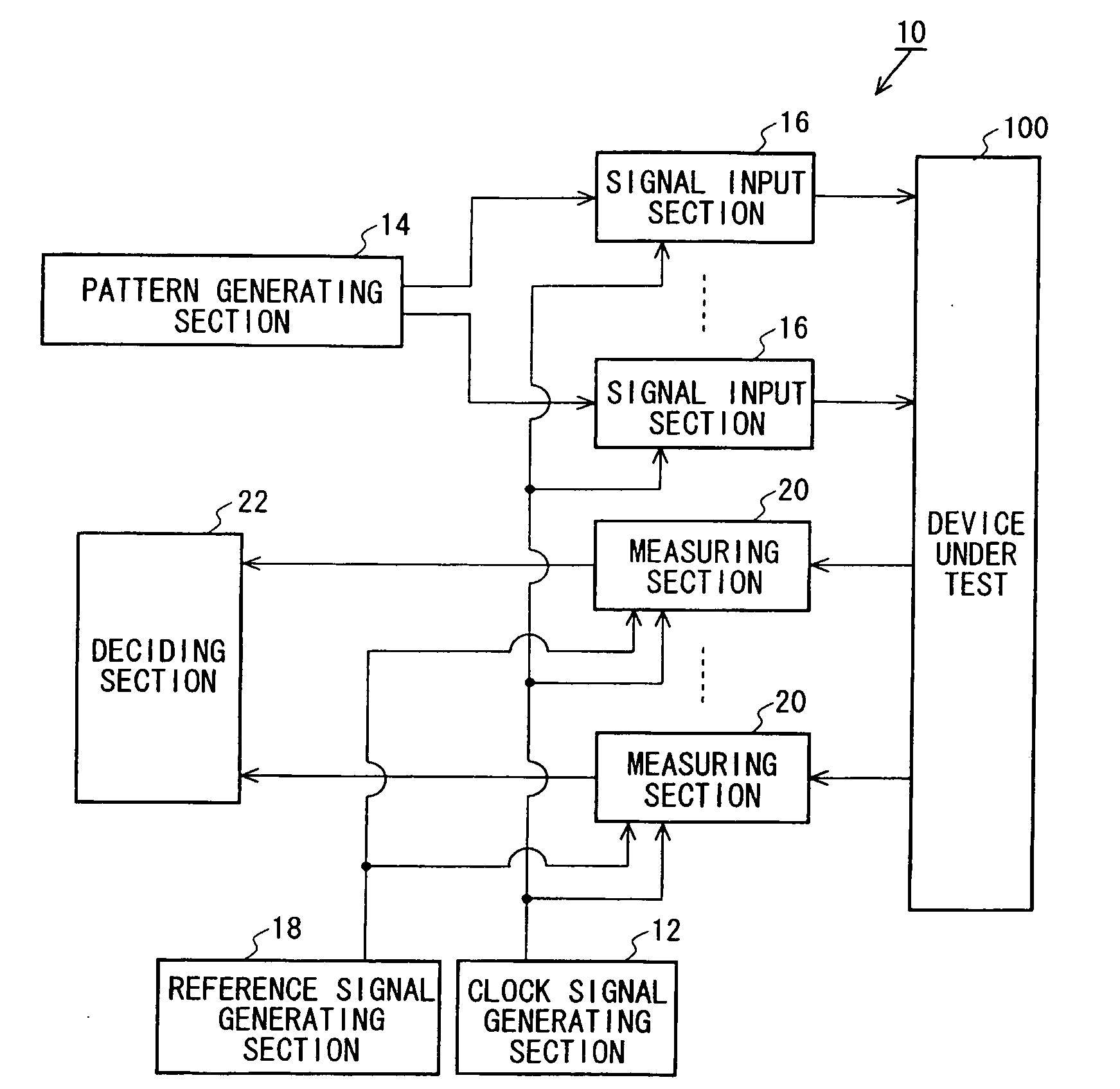
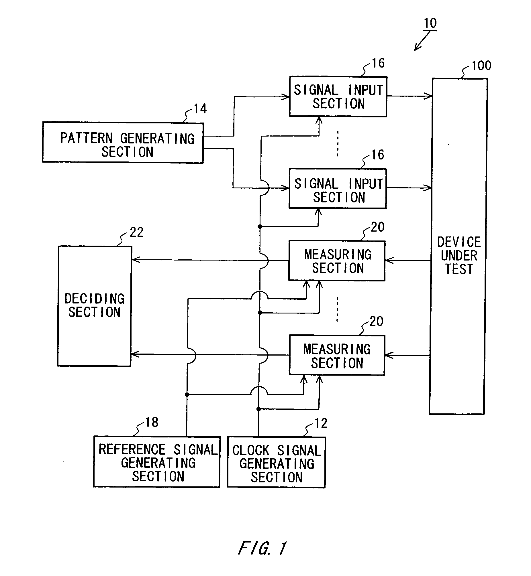
[0020]FIG. 1 is a view showing a configuration of a test apparatus 10 according to an embodiment of the present invention along with a device under test 100. The test apparatus 10 acquires an output signal output from the device under test 100, and decides the good or bad of the acquired signal to test the device under test 100. Furthermore, the test apparatus 10 can selectively acquire an output signal output in accordance with a test signal without including therein a clock and an output signal as a periodic signal including therein a clock, from the same pin of the device under test 100.

[0021]The test apparatus 10 includes a clock signal generating section 12, a pat...


PUM


Abstract

There is provided an electric circuit that outputs a timing signal and a recovered clock. The electric circuit includes a delay circuit that delays a reference signal, a PLL section that delays an oscillation signal synchronized with the delayed reference signal by an offset delay amount to output the delayed oscillation signal when outputting the timing signal and changes a delay amount for the oscillation signal in a tracking range using the offset delay amount as a standard to output the oscillation signal in synchronization with a periodic signal when outputting the recovered clock, a delay amount separating section that separates a coarse component of an integral multiple of a period of the clock signal and a fine component less than the period of the clock signal from a system timing, and a delay setting section that sets a value obtained by subtracting an adjusted delay amount, which is an integral multiple of the period of the clock signal, from the coarse component as the delay amount of the delay circuit and sets a value obtained by adding the adjusted delay amount to the fine component as the offset delay amount if the tracking range in a negative direction is larger than the fine component.

Description

CROSS REFERENCE TO RELATED APPLICATION[0001]The present application claims priority from a Japanese Patent Application No. 2006-198113 filed on Jul. 20, 2006, the contents of which are incorporated herein by reference.BACKGROUND[0002]1. Technical Field[0003]The present invention relates to an electric circuit and a test apparatus. More particularly, the present invention relates to an electric circuit that outputs a recovered clock synchronized with a given periodic signal and a test apparatus that tests a device under test by means of a recovered clock obtained by regenerating an output signal output from the device under test.[0004]2. Related Art[0005]A test apparatus acquires an output signal output from a device under test through a timing comparator, and decides the good or bad for the acquired signal. When testing a device outputting an output signal in accordance with the application of an input signal, the test apparatus acquires the output signal at a timing at which a refe...

Claims


Application Information

Patent Timeline
Patent Type & Authority Applications(United States)
IPC IPC(8): G01R27/28H03L7/06
CPCH03L7/0807H03L7/087H04L7/0033H04L7/033H03L7/189
Inventor CHIBA, NORIAKIOCHI, TAKASHI
Owner ADVANTEST CORP
Why Eureka
Try Eureka